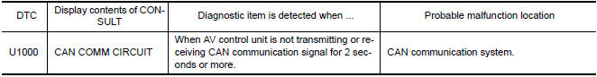
Nissan Maxima Service and Repair Manual: U1000 CAN comm circuit
Description
CAN (Controller Area Network) is a serial communication line for real time application. It is an on-vehicle multiplex communication line with high data communication speed and excellent error detection ability. Many electronic control units are equipped on a vehicle and each control unit shares information and links with other control units during operation (not independent). In CAN communication, control units are connected with 2 communication lines (CAN-H, CAN-L) allowing a high rate of information transmission with less wiring. Each control unit transmits/receives data but selectively reads required data only.
DTC Logic
DTC DETECTION LOGIC
Diagnosis Procedure
1.PERFORM SELF DIAGNOSTIC
- Turn ignition switch ON and wait for 2 seconds or more.
- Check "Self Diagnostic Result" of "AV Control Unit".

 U1010 control unit (CAN)
Description
Initial diagnosis of AV control unit.
DTC Logic
DTC DETECTION LOGIC
Diagnosis Procedure
1.REPLACE AV CONTROL UNIT ...
Other materials:
Condenser
CONDENSER
CONDENSER : Removal and Installation
REMOVAL
Discharge the refrigerant. Refer to HA-28, "Recycle Refrigerant".
Remove the RH hoodledge cover.
Remove the front bumper fascia. Refer to EXT-16, "Removal and
Installation".
Disconnect the high-pressure pipe from the condenser pip ...
Driver side door mirror defogger does not operate
Diagnosis Procedure
1. CHECK DOOR MIRROR DEFOGGER LH
Check door mirror defogger LH.
PASSENGER SIDE DOOR MIRROR DEFOGGER DOES NOT OPERATE
Diagnosis Procedure
1. CHECK DOOR MIRROR DEFOGGER RH
Check door mirror defogger RH.
REAR WINDOW DEFOGGER SWITCH DOES NOT LIGHT, BUT REAR WINDOW
DEFOGGER O ...
C1712 - C1715, C1720 - C1723, C1724 - C1727 transmitter malfunction
Description
One or more transmitters are malfunctioning internally.
DTC Logic
NOTE: The Signal Tech II Tool (J-50190) can be used
to perform the following functions. Refer to the Signal Tech II User Guide
for additional information.
Activate and display TPMS transmitter IDs
...
Nissan Maxima Owners Manual
- Illustrated table of contents
- Safety-Seats, seat belts and supplemental restraint system
- Instruments and controls
- Pre-driving checks and adjustments
- Monitor, climate, audio, phone and voice recognition systems
- Starting and driving
- In case of emergency
- Appearance and care
- Do-it-yourself
- Maintenance and schedules
- Technical and consumer information
Nissan Maxima Service and Repair Manual

0.0094