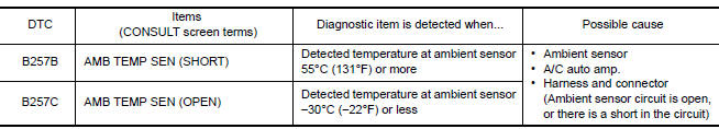
Nissan Maxima Service and Repair Manual: B257B, B257C ambient sensor
Description
COMPONENT DESCRIPTION
Ambient Sensor
- The ambient sensor (1) is installed to the front bumper reinforcement.
- It detects ambient temperature and converts it into a resistance value which is then input into the A/C auto amp.
Ambient Sensor Circuit
AMBIENT TEMPERATURE INPUT PROCESS
The A/C auto amp. equips a processing circuit for the ambient sensor input. However, when the temperature detected by the ambient sensor increases quickly, the processing circuit retards the A/C auto amp. function. It only allows the A/C auto amp. to recognize an ambient temperature increase of 0.33C (0.6F) per 100 seconds.
As an example, consider stopping for a few minutes after high speed driving. Although the actual ambient temperature has not changed, the temperature detected by the ambient sensor increases. This is because the heat from the engine compartment can radiate to the front bumper area, the location of the ambient sensor.
DTC Logic
DTC DETECTION LOGIC
NOTE:
- If DTC is displayed along with DTC U1000 or U1010, first diagnose the DTC U1000 or U1010. Refer to HAC- 133, "DTC Logic" or HAC-134, "DTC Logic".
- If there is an open circuit in the ambient sensor, A/C auto amp. registers extreme cold [-30C (-22F)] and adjusts the temperature control warmer.
DTC CONFIRMATION PROCEDURE
1.CHECK WITH SELF-DIAGNOSIS FUNCTION OF CONSULT
- Using CONSULT perform "SELF-DIAGNOSIS RESULTS" of HVAC.
- Check if any DTC No. is displayed in the self-diagnosis results.
NOTE:
- If DTC is displayed along with DTC U1000 or U1010, first diagnose the DTC U1000 or U1010. Refer to HAC- 133, "DTC Logic" or HAC-134, "DTC Logic".
- If there is an open circuit in the ambient sensor, A/C auto amp. registers extreme cold [-30C (-22F)] and adjusts the temperature control warmer.
Diagnosis Procedure
1.CHECK VOLTAGE BETWEEN AMBIENT SENSOR AND GROUND
- Disconnect ambient sensor connector.
- Turn ignition switch ON.
- Check voltage between ambient sensor harness connector E211 terminal 1 and ground.
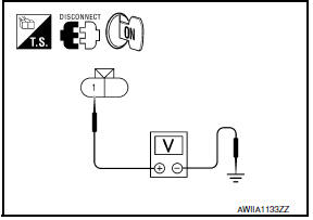
1 - Ground: Approx. 5V
2.CHECK CONTINUITY BETWEEN AMBIENT SENSOR AND A/C AUTO AMP.
- Turn ignition switch OFF.
- Disconnect A/C auto amp. connector.
- Check continuity between ambient sensor harness connector E211 (A) terminal 2 and A/C auto amp. harness connector M37 (B) terminal 37.
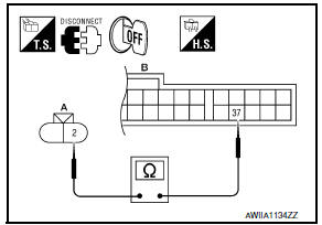
2 - 37: Continuity should exist.
3.CHECK AMBIENT SENSOR
Check ambient sensor.
4.CHECK CONTINUITY BETWEEN AMBIENT SENSOR AND A/C AUTO AMP
- Turn ignition switch OFF.
- Disconnect A/C auto amp. connector.
- Check continuity between ambient sensor harness connector E211 (A) terminal 1 and A/C auto amp. harness connector M37 (B) terminal 35.
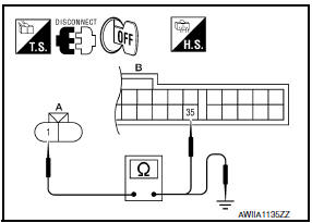
1 - 35: Continuity should exist.
- Check continuity between ambient sensor harness connector E211 (A) terminal 1 and ground.
1 - Ground: Continuity should not exist.
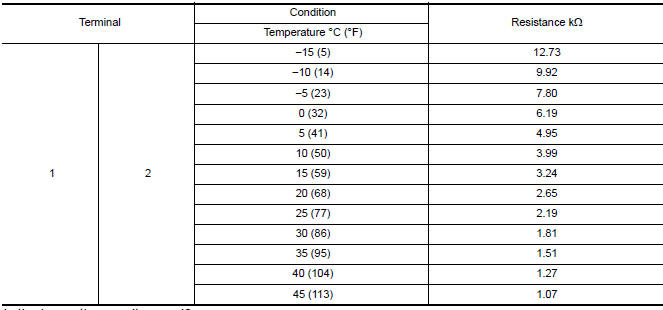
Component Inspection
1.CHECK AMBIENT SENSOR
- Turn ignition switch OFF.
- Disconnect ambient sensor connector.
- Check resistance between ambient sensor terminals.
 U1010 control unit (CAN)
Description
Initial diagnosis of A/C auto amp.
DTC Logic
DTC DETECTION LOGIC
Diagnosis Procedure
1.CHECK WITH SELF-DIAGNOSIS FUNCTION OF CONSULT
Using CONSULT, perform "SELF-DIAGNOSIS RESULT ...
 B2578, B2579 in-vehicle sensor
Description
In-vehicle Sensor
The in-vehicle sensor (1) is located on instrument lower cover
(LH).
It converts variations in compartment air temperature drawn from
the aspirator into a ...
Other materials:
U1000 CAN comm circuit
Description
DTC Logic
DTC DETECTION LOGIC
NOTE:
U1000 can be set if a module harness was disconnected and reconnected, perhaps
during a repair. Confirm
that there are actual CAN diagnostic symptoms and a present DTC by performing
the Self Diagnostic Result
procedure.
Diagnosis Proc ...
Tilt sensor
Description
The tilt sensor is installed to the steering column assembly.
The pulse signal is input to the driver seat control unit when the tilt
is operated.
The driver seat control unit counts the pulse and calculates the
tilt amount of the steering column.
Component Function Chec ...
On board diagnostic (OBD) system
Diagnosis Description
This system is an on board diagnostic system that records exhaust
emission-related diagnostic information
and detects a sensors/actuator-related malfunction. A malfunction is indicated
by the malfunction indicator
lamp (MIL) and stored in ECU memory as a DTC. The diagn ...
Nissan Maxima Owners Manual
- Illustrated table of contents
- Safety-Seats, seat belts and supplemental restraint system
- Instruments and controls
- Pre-driving checks and adjustments
- Monitor, climate, audio, phone and voice recognition systems
- Starting and driving
- In case of emergency
- Appearance and care
- Do-it-yourself
- Maintenance and schedules
- Technical and consumer information
Nissan Maxima Service and Repair Manual

0.0059