
Nissan Maxima Service and Repair Manual: Satellite radio antenna
Removal and Installation
REMOVAL
- Lower the headlining at the rear. Refer to INT-33, "Exploded View".
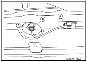
- Disconnect the harness connector (A) from satellite radio antenna.
- Remove the satellite radio antenna nut (B) and the satellite radio antenna (1).
INSTALLATION
Installation is in the reverse order of removal.
 Bose speaker AMP
Removal and Installation
Bose speaker amp.
Screws
REMOVAL
NOTE:
If removing the BOSE speaker amp. bracket, it is necessary to remove the parcel
shelf finisher. The BOSE
speaker am ...
 GPS antenna
Removal and Installation
REMOVAL
Remove cluster lid A. Refer to IP-10, "Exploded View".
Remove the audio unit. Refer to AV-652, "Removal and
Installation".
Remove t ...
Other materials:
P0776 pressure control solenoid B
Description
The secondary pressure solenoid valve regulates the secondary pressure to
suit the driving condition in
response to a signal sent from the TCM.
DTC Logic
DTC DETECTION LOGIC
DTC CONFIRMATION PROCEDURE
CAUTION:
Always drive vehicle at a safe speed.
NOTE:
Immediately after ...
Front door finisher
Exploded View
Mirror cover
Front door finisher
Step lamp
Arm rest finisher
Main power window and door lock/ unlock switch finisher
Front door grip cover
Seat memory switch (if equipped)
Inside release handle escutcheon
Inside release handle
Flat head screws
&nbs ...
P1550 battery current sensor
Description
The power generation voltage variable control enables fuel consumption to be
decreased by reducing the
engine load which is caused by the power generation of the generator. The
battery current sensor is installed
to the battery cable at the negative terminal. The sensor measures ...
Nissan Maxima Owners Manual
- Illustrated table of contents
- Safety-Seats, seat belts and supplemental restraint system
- Instruments and controls
- Pre-driving checks and adjustments
- Monitor, climate, audio, phone and voice recognition systems
- Starting and driving
- In case of emergency
- Appearance and care
- Do-it-yourself
- Maintenance and schedules
- Technical and consumer information
Nissan Maxima Service and Repair Manual

0.009