Nissan Maxima Service and Repair Manual: P1226 TP sensor
Description
Electric throttle control actuator consists of throttle control motor, throttle position sensor, etc. The throttle position sensor responds to the throttle valve movement.
The throttle position sensor has two sensors. These sensors are a kind of potentiometer which transform the throttle valve position into output voltage, and emit the voltage signal to the ECM. The ECM judges the current opening angle of the throttle valve from these signals and controls the throttle valve opening angle in response to driving conditions via the throttle control motor
DTC Logic
DTC DETECTION LOGIC

TC CONFIRMATION PROCEDURE
1.PRECONDITIONING
If DTC Confirmation Procedure has been previously conducted, always perform the following before conducting the next test.
- Turn ignition switch OFF and wait at least 10 seconds.
- Turn ignition switch ON.
- Turn ignition switch OFF and wait at least 10 seconds.
TESTING CONDITION: Before performing the following procedure, confirm that battery voltage is more than 10 V at idle.
2.PERFORM DTC CONFIRMATION PROCEDURE
- Turn ignition switch ON.
- Turn ignition switch OFF and wait at least 10 seconds.
- Turn ignition switch ON.
- Repeat steps 2 and 3 for 32 times.
- Check 1st trip DTC.
Diagnosis Procedure
1.CHECK ELECTRIC THROTTLE CONTROL ACTUATOR VISUALLY
- Turn ignition switch OFF.
- Remove the intake air duct.
- Check if foreign matter is caught between the throttle valve (1) and the housing
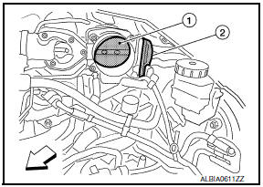
2: Electric throttle control actuator
 : Vehicle front
2.REPLACE ELECTRIC THROTTLE CONTROL ACTUATOR
1. Replace electric throttle control actuator.
Special Repair Requirement
1.PERFORM THROTTLE VALVE CLOSED POSITION LEARNING
2.PERFORM IDLE AIR VOLUME LEARNING
 P1225 TP sensor
Description
Electric throttle control actuator consists of throttle control motor,
throttle position sensor, etc. The throttle position sensor responds to
the throttle valve movement.
The ...
 P1550 battery current sensor
Description
The power generation voltage variable control enables fuel consumption to be
decreased by reducing the
engine load which is caused by the power generation of the generator. The
batt ...
Other materials:
Measurement of weights
Secure loose items to prevent weight
shifts that could affect the balance of your
vehicle. When the vehicle is loaded, drive
to a scale and weigh the front and the rear
wheels separately to determine axle
loads. Individual axle loads should not exceed
either of the gross axle weight ratings
( ...
Front tweeter
Removal and Installation
REMOVAL
Remove the front pillar finisher. Refer to INT-24, "Removal and
Installation".
Remove the front tweeter speaker grille. Refer to IP-10, "Exploded
View".
Remove the front tweeter speaker screws (A).
Pull out front tweeter speaker (1), disconnect the ...
Glass lid
Removal and Installation
REMOVAL
CAUTION:
Always work with a helper.
Handle glass lid with care to prevent damage.
NOTE: For easier and more accurate
installation, always mark each point before removal.
Open sunshade.
Tilt glass lid up, then slide rearward to expose all the g ...
Nissan Maxima Owners Manual
- Illustrated table of contents
- Safety-Seats, seat belts and supplemental restraint system
- Instruments and controls
- Pre-driving checks and adjustments
- Monitor, climate, audio, phone and voice recognition systems
- Starting and driving
- In case of emergency
- Appearance and care
- Do-it-yourself
- Maintenance and schedules
- Technical and consumer information
Nissan Maxima Service and Repair Manual

0.0061