
Nissan Maxima Service and Repair Manual: P1225 TP sensor
Description
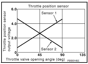
Electric throttle control actuator consists of throttle control motor, throttle position sensor, etc. The throttle position sensor responds to the throttle valve movement.
The throttle position sensor has two sensors. These sensors are a kind of potentiometer which transform the throttle valve position into output voltage, and emit the voltage signal to the ECM. The ECM judges the current opening angle of the throttle valve from these signals and controls the throttle valve opening angle in response to driving conditions via the throttle control motor.
DTC Logic
DTC DETECTION LOGIC

DTC CONFIRMATION PROCEDURE
1.PRECONDITIONING
If DTC Confirmation Procedure has been previously conducted, always perform the following before conducting the next test.
- Turn ignition switch OFF and wait at least 10 seconds.
- Turn ignition switch ON.
- Turn ignition switch OFF and wait at least 10 seconds.
TESTING CONDITION: Before performing the following procedure, confirm that battery voltage is more than 10 V at idle.
2.PERFORM DTC CONFIRMATION PROCEDURE
- Turn ignition switch ON.
- Turn ignition switch OFF and wait at least 10 seconds.
- Turn ignition switch ON.
- Check 1st trip DTC.
Diagnosis Procedure
1.CHECK ELECTRIC THROTTLE CONTROL ACTUATOR VISUALLY
- Turn ignition switch OFF.
- Remove the intake air duct.
- Check if foreign matter is caught between the throttle valve (1) and the housing.
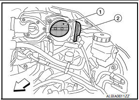
2: Electric throttle control actuator
 : Vehicle front
2.REPLACE ELECTRIC THROTTLE CONTROL ACTUATOR
- Replace electric throttle control actuator.
Special Repair Requirement
1.PERFORM THROTTLE VALVE CLOSED POSITION LEARNING
2.PERFORM IDLE AIR VOLUME LEARNING
 P1217 engine over temperature
DTC Logic
DTC DETECTION LOGIC
NOTE:
If DTC P1217 is displayed with DTC UXXXX, first perform the
trouble diagnosis for DTC UXXXX.
Refer to EC-161, "DTC Logic".
If DTC ...
 P1226 TP sensor
Description
Electric throttle control actuator consists of throttle control motor,
throttle position sensor, etc. The throttle position sensor responds to
the throttle valve movement.
The ...
Other materials:
Power window and door lock/unlock switch RH
Reference Value
TERMINAL LAYOUT
PHYSICAL VALUES
POWER WINDOW AND DOOR LOCK/UNLOCK SWITCH RH
Fail Safe
FAIL-SAFE CONTROL
Switches to fail-safe control when malfunction is detected in encoder signal
that detects up/down speed and
direction of door glass. Switches to fail-safe con ...
P1212 TCS communication line
Description
This CAN communication line is used to control the smooth engine operation
during the TCS operation. Pulse
signals are exchanged between ECM and "ABS actuator and electric unit (control
unit)".
Be sure to erase the malfunction information such as DTC not only for "ABS
actuato ...
Loose fuel cap warning
The LOOSE FUEL CAP warning appears in the
vehicle information display when the fuel-filler
cap is not tightened correctly after the vehicle has
been refueled. It may take a few driving trips for
the message to be displayed. To turn off the
warning, perform the following:
1. Remove and inst ...
Nissan Maxima Owners Manual
- Illustrated table of contents
- Safety-Seats, seat belts and supplemental restraint system
- Instruments and controls
- Pre-driving checks and adjustments
- Monitor, climate, audio, phone and voice recognition systems
- Starting and driving
- In case of emergency
- Appearance and care
- Do-it-yourself
- Maintenance and schedules
- Technical and consumer information
Nissan Maxima Service and Repair Manual

0.0124