Nissan Maxima Service and Repair Manual: Inspection and adjustment
BASIC INSPECTION
BASIC INSPECTION : Special Repair Requirement
1.INSPECTION START
- Check service records for any recent repairs that may indicate a related malfunction, or a current need for scheduled maintenance.
- Open engine hood and check the following:
- Harness connectors for improper connections
- Wiring harness for improper connections, pinches and cut
- Vacuum hoses for splits, kinks and improper connections
- Hoses and ducts for leakage
- Air cleaner clogging
- Gasket
- Check that electrical or mechanical loads are not applied.
- Head lamp switch is OFF.
- Air conditioner switch is OFF.
- Rear window defogger switch is OFF.
- Steering wheel is in the straight-ahead position, etc.
- Start engine and warm it up until engine coolant temperature
indicator points to the middle of gauge.
Ensure engine stays below 1,000 rpm.
- Run engine at about 2,000 rpm for about 2 minutes under no load.
- Check that no DTC is displayed with CONSULT or GST.
2.REPAIR OR REPLACE
Repair or replace components as necessary according to corresponding Diagnostic Procedure.
3.CHECK TARGET IDLE SPEED
- Run engine at about 2,000 rpm for about 2 minutes under no load.
- Rev engine between 2,000 and 3,000 rpm two or three times under no load, then run engine at idle speed for about 1 minute.
- Check idle speed.
4.PERFORM ACCELERATOR PEDAL RELEASED POSITION LEARNING
- Stop engine.
5.PERFORM THROTTLE VALVE CLOSED POSITION LEARNING
6.PERFORM IDLE AIR VOLUME LEARNING
7.CHECK TARGET IDLE SPEED AGAIN
- Start engine and warm it up to normal operating temperature.
- Check idle speed.
8.DETECT MALFUNCTIONING PART
Check the Following.
- Check camshaft position sensor (PHASE) and circuit. Refer to EC-301, "Diagnosis Procedure".
- Check crankshaft position sensor (POS) and circuit.
9.CHECK ECM FUNCTION
- Substitute with a non-malfunctioning ECM to check ECM function. (ECM may be the cause of the incident, although this is rare.)
- Perform initialization of NVIS (NATS) system and registration of all NVIS (NATS) ignition key IDs.
10.CHECK IGNITION TIMING
- Run engine at idle.
- Check ignition timing with a timing light.
11.PERFORM ACCELERATOR PEDAL RELEASED POSITION LEARNING
- Stop engine.
12.PERFORM THROTTLE VALVE CLOSED POSITION LEARNING
13.PERFORM IDLE AIR VOLUME LEARNING
14.CHECK TARGET IDLE SPEED AGAIN
- Start engine and warm it up to normal operating temperature.
- Check idle speed.
15.CHECK IGNITION TIMING AGAIN
- Run engine at idle.
- Check ignition timing with a timing light.
16.CHECK TIMING CHAIN INSTALLATION
Check timing chain installation
17.DETECT MALFUNCTIONING PART
Check the following.
- Check camshaft position sensor (PHASE) and circuit. Refer to EC-301, "Diagnosis Procedure".
- Check crankshaft position sensor (POS) and circuit.
18.CHECK ECM FUNCTION
- Substitute with a non-malfunctioning ECM to check ECM function. (ECM may be the cause of the incident, although this is rare.)
- Perform initialization of NVIS (NATS) system and registration of all NVIS (NATS) ignition key IDs.
19.INSPECTION END
Did you replace ECM, referring this Basic Inspection procedure?
ADDITIONAL SERVICE WHEN REPLACING CONTROL UNIT
ADDITIONAL SERVICE WHEN REPLACING CONTROL UNIT : Description
When replacing ECM, the following procedure must be performed. (For details, refer to EC-17, "ADDITIONAL SERVICE WHEN REPLACING CONTROL UNIT : Special Repair Requirement".)
PROGRAMMING OPERATION
NOTE: After replacing with a blank ECM, programming is required to write ECM information. Be sure to follow the procedure to perform the programming.
ADDITIONAL SERVICE WHEN REPLACING CONTROL UNIT : Special Repair Requirement
1.SAVE ECM DATA
With CONSULT
- Turn ignition switch OFF.
- Reconnect all harness connectors disconnected.
- Turn ignition switch ON.
- Select "SAVING DATA FOR REPLC CPU" in "WORK SUPPORT" mode of "ENGINE" using CONSULT.
- Follow the instruction of CONSULT display.
NOTE:
- Necessary data in ECM is copied and saved to CONSULT.
- Go to Step 2 regardless of with or without success in saving data.
2.CHECK ECM PART NUMBER
Check ECM part number to see whether it is blank ECM or not.
NOTE:
- Part number of blank ECM is 23703 - ×××××.
- Check part number when ordering ECM or the one included in the label on the container box.
3.SAVE ECM PART NUMBER
Read out the part number from the old ECM and save the number, following the programming instructions.
Refer to CONSULT Operation Manual.
NOTE:
- The ECM part number is saved in CONSULT.
- Even when ECM part number is not saved in CONSULT, go to 4.
4.PERFORM ECM PROGRAMMING
After replacing ECM, perform the ECM programming. Refer to CONSULT Operation Manual.
NOTE: During programming, maintain the following conditions:
- Ignition switch: ON
- Electric load: OFF
- Brake pedal: Not depressed
- Battery voltage: 12 - 13.5 V (Be sure to check the value of battery voltage by selecting "BATTERY VOLT" in "Data monitor" of CONSULT.)
5.REPLACE ECM
Replace ECM.
6.PERFORM INITIALIZATION OF IVIS (NATS) SYSTEM AND REGISTRATION OF ALL IVIS (NATS) IGNITION KEY IDS
7.CHECK ECM DATA STATUS
Check if the data is successfully copied from the ECM at Step 1 (before replacement) and saved in CONSULT.
8.WRITE ECM DATA
With CONSULT
- Select "WRITING DATA FOR REPLC CPU" in "WORK SUPPORT" mode of "ENGINE" using CONSULT.
- Follow the instruction of CONSULT display.
NOTE: The data saved by "SAVING DATA FOR REPLC CPU" is written to ECM.
9.PERFORM VIN REGISTRATION
10.PERFORM ACCELERATOR PEDAL RELEASED POSITION LEARNING
Perform Accelerator Pedal Released Position Learning.
11.PERFORM THROTTLE VALVE CLOSED POSITION LEARNING
Perform Throttle Valve Closed Position Learning
12.PERFORM IDLE AIR VOLUME LEARNING
Perform Idle Air Volume Learning
13.PERFORM EXHAUST VALVE TIMING CONTROL LEARNING
Perform exhaust valve timing control learning
IDLE SPEED
IDLE SPEED : Description
This describes how to check the idle speed. For the actual procedure, follow the instructions in "BASIC INSPECTION".
IDLE SPEED : Special Repair Requirement
1.CHECK IDLE SPEED
With CONSULT
Check idle speed in "DATA MONITOR" mode with CONSULT.
With GST
Check idle speed with Service $01 of GST.
IGNITION TIMING
IGNITION TIMING : Description
This describes how to check the ignition timing. For the actual procedure, follow the instructions in "BASIC INSPECTION".
IGNITION TIMING : Special Repair Requirement
1.CHECK IGNITION TIMING
1. Attach timing light to loop wires as shown.
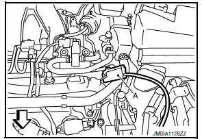
- : Timing light
 : Vehicle front
- Check ignition timing.
VIN REGISTRATION
VIN REGISTRATION : Description
VIN Registration is an operation to register VIN in ECM. It must be performed each time ECM is replaced.
NOTE: Accurate VIN which is registered in ECM may be required for Inspection & Maintenance (I/M).
VIN REGISTRATION : Special Repair Requirement
1.CHECK VIN
Check the VIN of the vehicle and note it.
2.PERFORM VIN REGISTRATION
With CONSULT
- Turn ignition switch ON and engine stopped.
- Select "VIN REGISTRATION" in "WORK SUPPORT" mode.
- Follow the instruction of CONSULT display.
ACCELERATOR PEDAL RELEASED POSITION LEARNING
ACCELERATOR PEDAL RELEASED POSITION LEARNING : Description
Accelerator Pedal Released Position Learning is an operation to learn the fully released position of the accelerator pedal by monitoring the accelerator pedal position sensor output signal. It must be performed each time the harness connector of the accelerator pedal position sensor or ECM is disconnected.
ACCELERATOR PEDAL RELEASED POSITION LEARNING : Special Repair Requirement
1.START
- Check that accelerator pedal is fully released.
- Turn ignition switch ON and wait at least 2 seconds.
- Turn ignition switch OFF and wait at least 10 seconds.
- Turn ignition switch ON and wait at least 2 seconds.
- Turn ignition switch OFF and wait at least 10 seconds
THROTTLE VALVE CLOSED POSITION LEARNING
THROTTLE VALVE CLOSED POSITION LEARNING : Description
Throttle Valve Closed Position Learning is an operation to learn the fully closed position of the throttle valve by monitoring the throttle position sensor output signal. It must be performed each time harness connector of electric throttle control actuator or ECM is disconnected or electric throttle control actuator is cleaned.
THROTTLE VALVE CLOSED POSITION LEARNING : Special Repair Requirement
1.START
WITH CONSULT
- Turn ignition switch ON.
- Select "CLSD THL POS LEARN" in "WORK SUPPORT" mode.
- Follow the instructions on the CONSULT display.
- Turn ignition switch OFF and wait at least 10 seconds.
Check that throttle valve moves during the above 10 seconds by confirming the operating sound.
WITHOUT CONSULT
- Start the engine. NOTE: Engine coolant temperature is 25C (77F) or less before engine starts.
- Warm up the engine. NOTE: Raise engine coolant temperature until it reaches 65C (149F) or more.
- Turn ignition switch OFF and wait at least 10 seconds.
Check that throttle valve moves during the above 10 seconds by confirming the operating sound.
IDLE AIR VOLUME LEARNING
IDLE AIR VOLUME LEARNING : Description
Idle Air Volume Learning is a function of ECM to learn the idle air volume that keeps engine idle speed within the specific range. It must be performed under the following conditions:
- Each time electric throttle control actuator or ECM is replaced.
- Idle speed or ignition timing is out of specification.
IDLE AIR VOLUME LEARNING : Special Repair Requirement
1.PRECONDITIONING
Before performing Idle Air Volume Learning, check that all of the following conditions are satisfied.
Learning will be cancelled if any of the following conditions are missed for even a moment.
- Battery voltage: More than 12.9 V (At idle)
- Engine coolant temperature: 70 - 100C (158 - 212F)
- Selector lever: P or N
- Electric load switch: OFF (Air conditioner, head lamp, rear window defogger) On vehicles equipped with daytime light systems, if the parking brake is applied before the engine is started the head lamp will not illuminate.
- Steering wheel: Neutral (Straight-ahead position)
- Vehicle speed: Stopped
- Transmission: Warmed-up
- With CONSULT: Drive vehicle until "ATF TEMP SEN" in "DATA MONITOR" mode of "CVT" system indicates less than 0.9 V.
- Without CONSULT: Drive vehicle for 10 minutes.
2.PERFORM IDLE AIR VOLUME LEARNING
With CONSULT
- Perform EC-20, "ACCELERATOR PEDAL RELEASED POSITION LEARNING : Special Repair Requirement".
- Perform EC-21, "THROTTLE VALVE CLOSED POSITION LEARNING : Special Repair Requirement".
- Start engine and warm it up to normal operating temperature.
- Select "IDLE AIR VOL LEARN" in "WORK SUPPORT" mode.
- Touch "START" and wait 20 seconds.
3.PERFORM IDLE AIR VOLUME LEARNING
Without CONSULT
NOTE:
- It is better to count the time accurately with a clock.
- It is impossible to switch the diagnostic mode when an accelerator pedal position sensor circuit has a malfunction.
- Perform EC-20, "ACCELERATOR PEDAL RELEASED POSITION LEARNING : Special Repair Requirement".
- Perform EC-21, "THROTTLE VALVE CLOSED POSITION LEARNING : Special Repair Requirement"
- Start engine and warm it up to normal operating temperature.
- Turn ignition switch OFF and wait at least 10 seconds.
- Confirm that accelerator pedal is fully released, turn ignition switch ON and wait 3 seconds.
- Repeat the following procedure quickly five times within 5 seconds.
- Fully depress the accelerator pedal.
- Fully release the accelerator pedal.
- Wait 7 seconds, fully depress the accelerator pedal for approx. 20 seconds until the MIL stops blinking and turns ON.
- Fully release the accelerator pedal within 3 seconds after the MIL turns ON.
- Start engine and let it idle.
- Wait 20 seconds.
4.CHECK IDLE SPEED AND IGNITION TIMING
Rev up the engine two or three times and check that idle speed and ignition timing are within the specifications
5.DETECT MALFUNCTIONING PART-I
Check the following
- Check that throttle valve is fully closed.
- Check PCV valve operation.
- Check that downstream of throttle valve is free from air leakage
6.DETECT MALFUNCTIONING PART-II
When the above three items check out OK, engine component parts and their installation condition are questionable.
Check and eliminate the cause of the incident.
It is useful to perform "TROUBLE DIAGNOSIS - SPECIFICATION VALUE". Refer to EC-149, "Description".
If any of the following conditions occur after the engine has started, eliminate the cause of the incident and perform Idle Air Volume Learning again:
- Engine stalls.
- Incorrect idle.
EXHAUST VALVE TIMING CONTROL LEARNING
EXHAUST VALVE TIMING CONTROL LEARNING : Description
Exhaust Valve Timing Control Learning is a function of ECM to learn the characteristic of exhaust valve timing control magnet retarder by comparing the target angle of exhaust camshaft with the actual retarded angle of exhaust camshaft. It must be performed each time exhaust valve timing control magnet retarder is disconnected or replaced, or ECM is replaced.
EXHAUST VALVE TIMING CONTROL LEARNING : Special Repair Requirement
1.START
With CONSULT
- Start engine and warm it up to normal operating temperature.
- Set selector lever position to N and confirm that the following electrical or mechanical loads are not applied.
- Headlamp switch is OFF
- Air conditioner switch is OFF
- Rear window defogger switch is OFF
- Steering wheel is in the straight-ahead position, etc.
- Keep the engine speed between 1,800 and 2,000 rpm.
- Select "EXH V/T CONTROL LEARN" in "WORK SUPPORT" mode with CONSULT.
- Touch "START" and wait 20 seconds.
- Check that "CMPLT" is displayed on CONSULT screen.
Learning completed : CMPLT
Learning not yet : YET
Without CONSULT
- Start engine and warm it up to normal operating temperature.
- Set selector lever position to N and confirm that the following electrical or mechanical loads are not applied.
- Headlamp switch is OFF
- Air conditioner switch is OFF
- Rear window defogger switch is OFF
- Steering wheel is in the straight-ahead position, etc.
- Keep the engine speed between 1,800 and 2,000 rpm at 20 seconds.
MIXTURE RATIO SELF-LEARNING VALUE CLEAR
MIXTURE RATIO SELF-LEARNING VALUE CLEAR : Description
This describes show to erase the mixture ratio self-learning value. For the actual procedure, follow the instructions in "Diagnosis Procedure".
MIXTURE RATIO SELF-LEARNING VALUE CLEAR : Special Repair Requirement
1.START
With CONSULT
- Start engine and warm it up to normal operating temperature.
- Select "SELF-LEARNING CONT" in "WORK SUPPORT" mode with CONSULT.
- Clear mixture ratio self-learning value by touching "CLEAR".
With GST
- Start engine and warm it up to normal operating temperature.
- Turn ignition switch OFF.
- Disconnect mass air flow sensor harness connector.
- Restart engine and let it idle for at least 5 seconds.
- Stop engine and reconnect mass air flow sensor harness connector.
- Select Service $03 with GST. Check that DTC P0102 is detected.
- Select Service $04 with GST to erase the DTC P0102.
 Diagnosis and repair work flow
Work Flow
OVERALL SEQUENCE
DETAILED FLOW
1.GET INFORMATION FOR SYMPTOM
Get the detailed information from the customer about the symptom
(the condition and the environment
when the inc ...
 How to set srt code
Description
OUTLINE
In order to set all SRTs, the self-diagnoses as in the "SRT ITEM" table must
have been performed at least
once. Each diagnosis may require actual driving for a long period of ...
Other materials:
Power seat for passenger side
Wiring Diagram
...
Children need adults to help protect them.
They need to be properly restrained.
In addition to the general information in this
manual, child safety information is available from
many other sources, including doctors, teachers,
government traffic safety offices, and community
organizations. Every child is different, so be sure
to lear ...
B1134 - B1137 side airbag module LH
Description
DTC B1134 - B1137 FRONT LH SIDE AIR BAG MODULE
The front LH side air bag module is wired to the air bag diagnosis sensor
unit. The air bag diagnosis sensorunit will monitor for opens and shorts in
detected lines to the front LH side air bag module.
PART LOCATION
DTC Logic
DTC DE ...
Nissan Maxima Owners Manual
- Illustrated table of contents
- Safety-Seats, seat belts and supplemental restraint system
- Instruments and controls
- Pre-driving checks and adjustments
- Monitor, climate, audio, phone and voice recognition systems
- Starting and driving
- In case of emergency
- Appearance and care
- Do-it-yourself
- Maintenance and schedules
- Technical and consumer information
Nissan Maxima Service and Repair Manual

0.0053