Nissan Maxima Service and Repair Manual: Diagnosis and repair work flow
Work Flow
OVERALL SEQUENCE
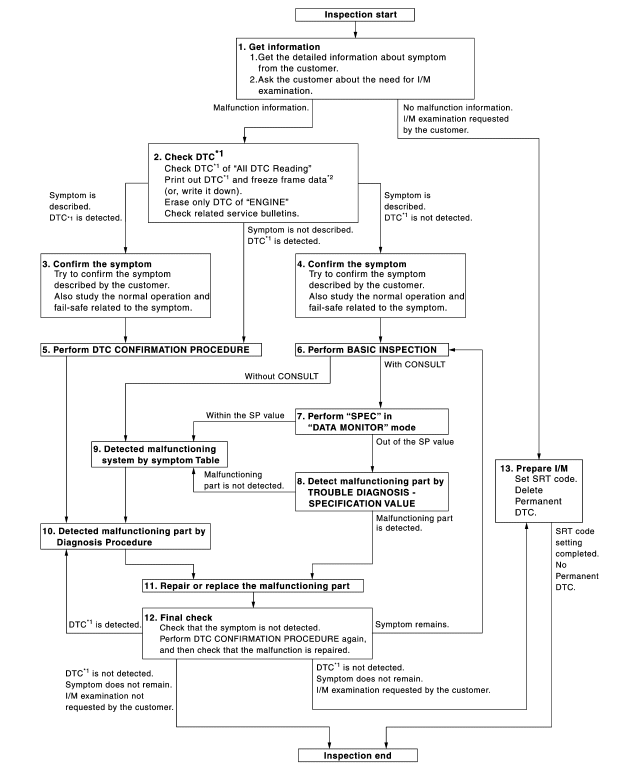
DETAILED FLOW
1.GET INFORMATION FOR SYMPTOM
- Get the detailed information from the customer about the symptom (the condition and the environment when the incident/malfunction occurred) using the "Diagnostic Work Sheet". (Refer to EC-12, "Diagnostic Work Sheet".)
- Ask if the customer requests I/M examination.
2.CHECK DTC
- Check DTC.
- Perform the following procedure if DTC is displayed.
- Record DTC and freeze frame data. (Print them out with CONSULT or GST.)
- Erase DTC. (Refer to EC-135, "On Board Diagnosis Function" or EC-138, "CONSULT Function".)
- Study the relationship between the cause detected by DTC and the
symptom described by the customer.
(Symptom Table is useful. Refer to EC-581, "Symptom Table".)
- Check related service bulletins for information.
3.CONFIRM THE SYMPTOM
Try to confirm the symptom described by the customer (except MIL ON).
Also study the normal operation and fail-safe related to the symptom.
Diagnosis Work Sheet is useful to verify the incident.
Verify relation between the symptom and the condition when the symptom is detected.
4.CONFIRM THE SYMPTOM
Try to confirm the symptom described by the customer.
Also study the normal operation and fail-safe related to the symptom. Refer to EC-585, "Description" and EC- 538, "Fail safe".
Diagnosis Work Sheet is useful to verify the incident.
Verify relation between the symptom and the condition when the symptom is detected.
5.PERFORM DTC CONFIRMATION PROCEDURE
Perform DTC CONFIRMATION PROCEDURE for the displayed DTC, and then check that DTC is detected again.
If two or more DTCs are detected, refer to EC-540, "DTC Inspection Priority Chart" and determine trouble diagnosis order.
NOTE:
- Freeze frame data is useful if the DTC is not detected.
- Perform Component Function Check if DTC CONFIRMATION PROCEDURE
is not included on Service
Manual. This simplified check procedure is an effective alternative though
DTC cannot be detected during
this check.
If the result of Component Function Check is NG, it is the same as the detection of DTC by DTC CONFIRMATION PROCEDURE.
6.PERFORM BASIC INSPECTION
7.PERFORM "SPEC" OF "DATA MONITOR" MODE
With CONSULT
Check that "MAS A/F SE-B1", "B/FUEL SCHDL", "A/F ALPHA-B1" and "A/F ALPHA-B2" are within the SP value using CONSULT in "SPEC" of "DATA MONITOR" mode.
8.DETECT MALFUNCTIONING PART BY TROUBLE DIAGNOSIS - SPECIFICATION VALUE
9.DETECT MALFUNCTIONING SYSTEM BY SYMPTOM TABLE
Detect malfunctioning system according to EC-581, "Symptom Table" based on the confirmed symptom in step 4, and determine the trouble diagnosis order based on possible causes and symptoms.
10.DETECT MALFUNCTIONING PART BY DIAGNOSTIC PROCEDURE
Inspect according to Diagnostic Procedure of the system.
NOTE: The Diagnostic Procedure in EC section described based on open circuit inspection. A short circuit inspection is also required for the circuit check in the Diagnostic Procedure. For details, refer to "Circuit Inspection" in GI- 44, "Circuit Inspection".
11.REPAIR OR REPLACE THE MALFUNCTIONING PART
- Repair or replace the malfunctioning part.
- Reconnect parts or connectors disconnected during Diagnostic Procedure again after repair and replacement.
- Check DTC. If DTC is displayed, erase it, refer to EC-135, "On Board Diagnosis Function" or EC-138, "CONSULT Function".
12.FINAL CHECK
When DTC was detected in step 2, perform DTC Confirmation Procedure or Overall Function Check again, and then check that the malfunction have been completely repaired.
When symptom was described from the customer, refer to confirmed symptom in step 3 or 4, and check that the symptom is not detected.
13.PREPARE FOR I/M EXAMINATION
- Set SRT codes. Refer to EC-26, "SRT Set Driving Pattern".
- Erase permanent DTCs
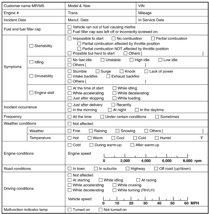
Diagnostic Work Sheet
DESCRIPTION
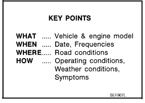
There are many operating conditions that lead to the malfunction of engine components. A good grasp of such conditions can make troubleshooting faster and more accurate.
In general, each customer feels differently about symptoms. It is important to fully understand the symptoms or conditions for a customer complaint.
Utilize a diagnostic worksheet like the WORKSHEET SAMPLE below in order to organize all the information for troubleshooting.
Some conditions may cause the MIL to illuminate or blink, and DTC to be detected. Examples:
- Vehicle ran out of fuel, which caused the engine to misfire.
- Fuel filler cap was left off or incorrectly screwed on, allowing fuel to evaporate into the atmosphere.
WORKSHEET SAMPLE
 Basic inspection
...
 Inspection and adjustment
BASIC INSPECTION
BASIC INSPECTION : Special Repair Requirement
1.INSPECTION START
Check service records for any recent repairs that may indicate a
related malfunction, or a current need f ...
Other materials:
P0725 engine speed
Description
The engine speed signal is transmitted from ECM to TCM via CAN communication
line.
DTC Logic
DTC DETECTION LOGIC
DTC CONFIRMATION PROCEDURE
CAUTION:
Always drive vehicle at a safe speed.
NOTE:
Immediately after performing any "DTC CONFIRMATION PROCEDURE", always turn
igni ...
Recommended fluids and lubricants
FOR USA AND CANADA
FOR USA AND CANADA : Fluids and Lubricants
*1: For further details, see "Engine Oil Recommendation".
*2: NISSAN recommends Genuine NISSAN Ester Oil available at a NISSAN dealer.
*3: Use only Genuine NISSAN CVT Fluid NS-2. Using transmission fluid other than
Genuine NIS ...
Text Messaging
Using the Bluetooth Hands-Free Phone System,
a received text message can be operated on
the vehicle information display as well as on the
touch-screen display.
To read/ignore an incoming text
1. When a new text message is received, a
pop-up window and operation keys will appear
with the sende ...
Nissan Maxima Owners Manual
- Illustrated table of contents
- Safety-Seats, seat belts and supplemental restraint system
- Instruments and controls
- Pre-driving checks and adjustments
- Monitor, climate, audio, phone and voice recognition systems
- Starting and driving
- In case of emergency
- Appearance and care
- Do-it-yourself
- Maintenance and schedules
- Technical and consumer information
Nissan Maxima Service and Repair Manual

0.0076