Nissan Maxima Service and Repair Manual: Cooler pipe and hose
Exploded View
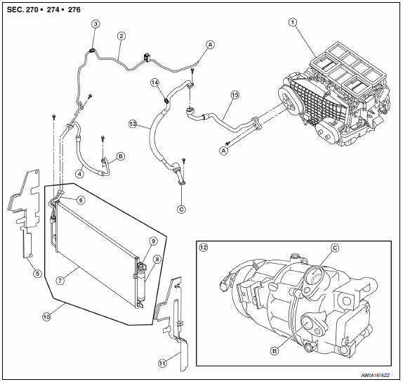
- Heater and cooling unit assembly
- High-pressure pipe
- High-pressure A/C service valve
- High-pressure flexible hose
- Air deflector (RH)
- Junction pipe
- Condenser
- Liquid tank
- Refrigerant pressure sensor
- Condenser, liquid tank and refrigerant pressure sensor
- Air deflector (LH)
- Compressor
- Low-pressure flexible hose
- Low-pressure A/C service valve
- Low-pressure pipe
- High-pressure pipe to heater and cooling unit assembly
- High-pressure flexible hose to compressor
- Low-pressure flexible hose to compressor
LOW-PRESSURE FLEXIBLE HOSE
LOW-PRESSURE FLEXIBLE HOSE : Removal and I
REMOVAL
CAUTION: Before servicing, turn the ignition switch off, disconnect both battery terminals and wait at least three minutes.
- Discharge the refrigerant.
- Partially drain the engine cooling system. Refer to CO-11, "Changing Engine Coolant".
- Disconnect the battery negative and positive terminals.
- Remove the engine room cover.
- Remove the air cleaner assembly and air ducts. Refer to EM-24, "Removal and Installation".
- Remove the upper radiator hose.
- Remove the battery and battery tray. Refer to PG-68, "Removal and Installation (Battery Tray)".
- Remove the engine cooling fan and shroud assembly. Refer to CO-17, "Removal and Installation".
- Disconnect the low-pressure flexible hose from the compressor and the low-pressure pipe. CAUTION: Cap or wrap the joint of the hose with suitable material such as vinyl tape to avoid the entry of air.
- Remove the low-pressure flexible hose.
INSTALLATION
Installation is in the reverse order of removal.
CAUTION:
- Do not reuse O-rings.
- Apply A/C oil to the new O-rings for installation.
- After recharging the refrigerant, check for leaks. Refer to HA-26, "Leak Test".
LOW-PRESSURE PIPE
LOW-PRESSURE PIPE : Removal and Installation
REMOVAL
- Discharge the refrigerant. Refer to HA-28, "Recycle Refrigerant".
- Remove the hoodledge covers (LH/RH).
- Remove the strut tower bar. Refer to FSU-13, "Exploded View".
- Remove the upper cowl. Refer to EXT-21, "Removal and Installation".
- Remove the lower RH cowl.
- Reposition the power steering reservoir out of the way without disconnecting the hose.
- Disconnect the power steering hose clamp to reposition the power steering hose out of the way without disconnecting the hose.
- Disconnect the low-pressure pipe from the expansion valve and the low-pressure hose.
CAUTION:
- Cap or wrap the joint of the pipe with a suitable material such as vinyl tape to avoid the entry of air.
- Remove the low-pressure pipe.
INSTALLATION
Installation is in the reverse order of removal.
CAUTION:
- Do not reuse O-rings.
- Apply A/C oil to the new O-rings for installation.
- - After recharging the refrigerant, check for leaks. Refer to HA-26, "Leak Test".
HIGH-PRESSURE FLEXIBLE HOSE
HIGH-PRESSURE FLEXIBLE HOSE : Removal and Installation
REMOVAL
CAUTION: Before servicing, turn the ignition switch off, disconnect both battery terminals and wait at least three minutes.
- Discharge the refrigerant. Refer to HA-28, "Recycle Refrigerant".
- Partially drain the engine cooling system. Refer to CO-11, "Changing Engine Coolant".
- Disconnect the battery negative and positive terminals.
- Remove the hoodledge covers (LH/RH).
- Remove the air cleaner assembly and air ducts. Refer to EM-24, "Removal and Installation".
- Remove the upper radiator hose.
- Remove the battery and battery tray. Refer to PG-68, "Removal and Installation (Battery Tray)".
- Remove the engine cooling fan and shroud assembly. Refer to CO-16, "Removal and Installation".
- Disconnect the high-pressure flexible hose from the compressor and the high-pressure pipe and junction pipe. CAUTION: Cap or wrap the joint of the hose with suitable material such as vinyl tape to avoid the entry of air.
- Remove the high-pressure flexible hose.
INSTALLATION
Installation is in the reverse order of removal.
CAUTION:
- Do not reuse O-rings.
- Apply A/C oil to the new O-rings for installation.
- After charging the refrigerant, check for leaks. Refer to HA-26, "Leak Test".
HIGH-PRESSURE PIPE
HIGH-PRESSURE PIPE : Removal and Installation
REMOVAL
- Discharge the refrigerant. Refer to HA-28, "Recycle Refrigerant".
- Remove the hoodledge covers (LH/RH).
- Remove the strut tower bar. Refer to FSU-13, "Exploded View".
- Remove the upper cowl. Refer to EXT-21, "Removal and Installation".
- Remove the lower RH cowl.
- Reposition the engine coolant reservoir out of the way without disconnecting the hose.
- Reposition the power steering reservoir out of the way without disconnecting the hose.
- Disconnect the power steering hose clamp to reposition the power steering hose out of the way without disconnecting the hose.
- Remove the torque rod. Refer to EM-103, "Removal and Installation".
- Disconnect the harness bracket from the engine cover.
- Disconnect the high-pressure pipe from the expansion valve and the high-pressure flexible hose and junction pipe. CAUTION: Cap or wrap the joint of the pipe with a suitable material such as vinyl tape to avoid the entry of air.
- Remove the high-pressure pipe.
INSTALLATION
Installation is in the reverse order of removal.
CAUTION:
- Do not reuse O-rings.
- Apply A/C oil to the new O-rings for installation.
- After charging the refrigerant, check for leaks. Refer to HA-26, "Leak Test".
 Removal and installation
COMPRESSOR
Removal and Installation for Compressor
REMOVAL
CAUTION: Before servicing, turn the ignition
switch off, disconnect both battery terminals and wait at least three
minutes.
Di ...
 Condenser
CONDENSER
CONDENSER : Removal and Installation
REMOVAL
Discharge the refrigerant. Refer to HA-28, "Recycle Refrigerant".
Remove the RH hoodledge cover.
Remove the front bumper fascia. Refer ...
Other materials:
P0607 ECM
Description
CAN (Controller Area Network) is a serial communication line for real time
application. It is an on-vehicle multiplex
communication line with high data communication speed and excellent error
detection ability. Many electronic
control units are equipped onto a vehicle, and each ...
Tilt switch
Description
ADP steering switch (tilt switch) is equipped to the steering column. The
operation signal is input to the automatic drive positioner control unit when
the tilt switch is operated.
Component Function Check
1. CHECK FUNCTION
Select "TILT SW-UP", "TILT SW-DOWN" in "DATA MONITOR" ...
Cowl top
Exploded View
Cowl top side trim cover (RH)
Cowl top grille
Lower cowl top extension brace
Lower cowl top extension (RH)
Lower cowl top extension seal (RH)
Lower cowl top extension seal (LH)
Lower cowl top extension (LH)
Front wiper drive assembly
Cowl top side trim cover ...
Nissan Maxima Owners Manual
- Illustrated table of contents
- Safety-Seats, seat belts and supplemental restraint system
- Instruments and controls
- Pre-driving checks and adjustments
- Monitor, climate, audio, phone and voice recognition systems
- Starting and driving
- In case of emergency
- Appearance and care
- Do-it-yourself
- Maintenance and schedules
- Technical and consumer information
Nissan Maxima Service and Repair Manual

0.0058