Nissan Maxima Service and Repair Manual: P0340, P0345 CMP sensor (PHASE)
Description
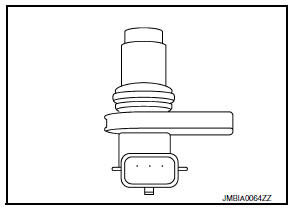
The camshaft position sensor (PHASE) senses the retraction of camshaft (INT) to identify a particular cylinder. The camshaft position sensor (PHASE) senses the piston position.
When the crankshaft position sensor (POS) system becomes inoperative, the camshaft position sensor (PHASE) provides various controls of engine parts instead, utilizing timing of cylinder identification signals.
The sensor consists of a permanent magnet and Hall IC.
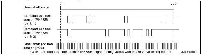
When engine is running, the high and low parts of the teeth cause the gap with the sensor to change.
The changing gap causes the magnetic field near the sensor to change.
Due to the changing magnetic field, the voltage from the sensor changes.
ECM receives the signals as shown in the figure.
DTC Logic
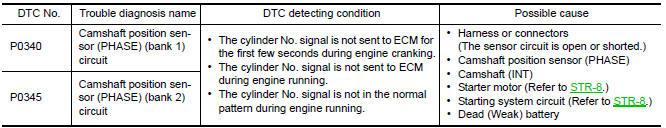
DTC DETECTION LOGIC
NOTE: If DTC P0340 or P0345 is displayed with DTC P0643, first perform the trouble diagnosis for DTC P0643.
DTC CONFIRMATION PROCEDURE
1.PRECONDITIONING
If DTC Confirmation Procedure has been previously conducted, always perform the following before conducting the next test.
- Turn ignition switch OFF and wait at least 10 seconds.
- Turn ignition switch ON.
- Turn ignition switch OFF and wait at least 10 seconds.
TESTING CONDITION: Before performing the following procedure, confirm that battery voltage is more than 10.5 V with ignition switch ON.
2.PERFORM DTC CONFIRMATION PROCEDURE-I
- Start engine and let it idle for at least 5 seconds.
If engine does not start, crank engine for at least 2 seconds.
- Check 1st trip DTC.
3.PERFORM DTC CONFIRMATION PROCEDURE-I
- Maintaining engine speed at more than 800 rpm for at least 5 seconds.
- Check 1st trip DTC.
Diagnosis Procedure
1.CHECK STARTING SYSTEM
Turn ignition switch to START position.
2.CHECK GROUND CONNECTION
- Turn ignition switch OFF.
- Check ground connection E9.
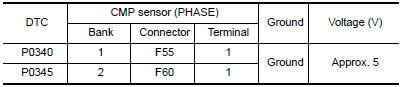
3.CHECK CAMSHAFT POSITION (CMP) SENSOR (PHASE) POWER SUPPLY CIRCUIT
- Disconnect camshaft position (CMP) sensor (PHASE) harness connector.
- Turn ignition switch ON.
- Check the voltage between CMP sensor (PHASE) harness connector and ground.
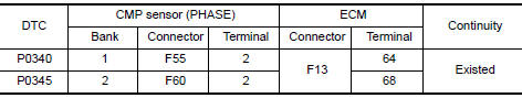
4.CHECK CMP SENSOR (PHASE) GROUND CIRCUIT FOR OPEN AND SHORT
- Turn ignition switch OFF.
- Disconnect ECM harness connector.
- Check the continuity between CMP sensor (PHASE) harness connector and ECM harness connector.
- Also check harness for short to ground and short to power.
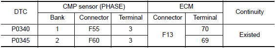
5.CHECK CMP SENSOR (PHASE) INPUT SIGNAL CIRCUIT FOR OPEN AND SHORT
- Check the continuity between CMP sensor (PHASE) harness connector and ECM harness connector.
- Also check harness for short to ground and short to power.
6.CHECK CAMSHAFT POSITION SENSOR (PHASE)
7.CHECK CAMSHAFT (INT)
Check the following.
- Accumulation of debris to the signal plate of camshaft rear end
- Chipping signal plate of camshaft rear end
8.CHECK INTERMITTENT INCIDENT
Component Inspection
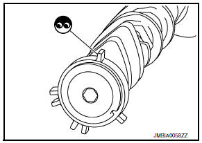
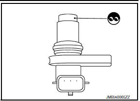
1.CHECK CAMSHAFT POSITION SENSOR (PHASE)-I
- Turn ignition switch OFF.
- Loosen the fixing bolt of the sensor.
- Disconnect camshaft position sensor (PHASE) harness connector.
- Remove the sensor.
- Visually check the sensor for chipping.
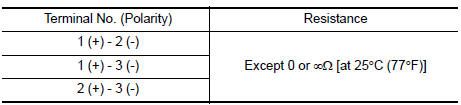
2.CHECK CAMSHAFT POSITION SENSOR (PHASE)-II
Check resistance camshaft position sensor (PHASE) terminals as per the following.
 P0335 CKP sensor (POS)
Description
The crankshaft position sensor (POS) is located on the oil pan facing
the gear teeth (cogs) of the signal plate. It detects the fluctuation of
the engine revolution.
The sensor ...
 P0420, P0430 three way catalyst function
DTC Logic
DTC DETECTION LOGIC
The ECM monitors the switching frequency ratio of air fuel ratio (A/F)
sensor 1 and heated oxygen sensor 2.
A three way catalyst (manifold) with high oxygen st ...
Other materials:
Air cleaner
The air cleaner filter should not be cleaned and
reused. Replace it according to the maintenance
log shown in the "Maintenance and schedules"
section of this manual. When replacing the filter,
wipe the inside of the air cleaner filter housing
and the cover with a damp cloth.
To remove the ...
Brake tube and hose
Hydraulic Circuit
Actuator
Master cylinder
Brake booster
Connector
Union bolt
18.2 N*m (1.9 kg-m, 13 ft-lb)
Flare nut M12
22.1 N*m (2.3 kg-m, 16 ft-lb)
Flare nut M10
16.2 N*m (1.7 kg-m, 12 ft-lb)
CAUTION:
All hoses and piping (tubes) must be free fr ...
C1145, C1146 yaw rate/side/decel G sensor
Description
The yaw rate/side/decel G sensor detects the yaw rate/side/decel G affecting
the vehicle, and transmits the
data to the ABS actuator and electric unit (control unit) as an analog voltage
signal.
DTC Logic
DTC DETECTION LOGIC
DTC CONFIRMATION PROCEDURE
1.CHECK SELF-DIAGNOSI ...
Nissan Maxima Owners Manual
- Illustrated table of contents
- Safety-Seats, seat belts and supplemental restraint system
- Instruments and controls
- Pre-driving checks and adjustments
- Monitor, climate, audio, phone and voice recognition systems
- Starting and driving
- In case of emergency
- Appearance and care
- Do-it-yourself
- Maintenance and schedules
- Technical and consumer information
Nissan Maxima Service and Repair Manual

0.0067