Nissan Maxima Service and Repair Manual: P0335 CKP sensor (POS)
Description
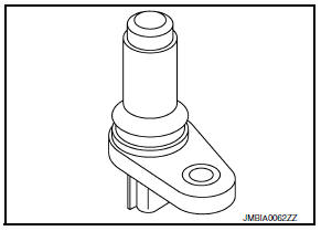
The crankshaft position sensor (POS) is located on the oil pan facing the gear teeth (cogs) of the signal plate. It detects the fluctuation of the engine revolution.
The sensor consists of a permanent magnet and Hall IC.
When the engine is running, the high and low parts of the teeth cause the gap with the sensor to change.
The changing gap causes the magnetic field near the sensor to change.
Due to the changing magnetic field, the voltage from the sensor changes.
The ECM receives the voltage signal and detects the fluctuation of the engine revolution.
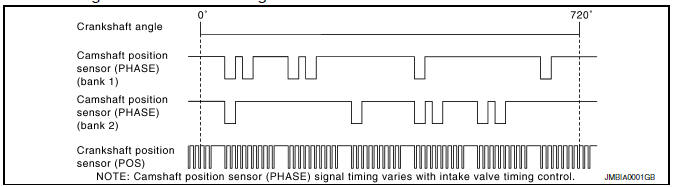
ECM receives the signals as shown in the figure.
DTC Logic
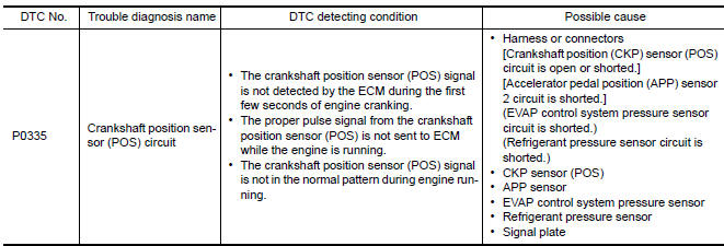
DTC DETECTION LOGIC
DTC CONFIRMATION PROCEDURE
1.PRECONDITIONING
If DTC Confirmation Procedure has been previously conducted, always perform the following before conducting the next test.
- Turn ignition switch OFF and wait at least 10 seconds.
- Turn ignition switch ON.
- Turn ignition switch OFF and wait at least 10 seconds.
TESTING CONDITION: Before performing the following procedure, confirm that battery voltage is more than 10.5 V with ignition switch ON.
2.PERFORM DTC CONFIRMATION PROCEDURE
- Start engine and let it idle for at least 5 seconds.
If engine does not start, crank engine for at least 2 seconds.
- Check 1st trip DTC.
Diagnosis Procedure
1.CHECK GROUND CONNECTION
- Turn ignition switch OFF.
- Check ground connection E9.
2.CHECK CRANKSHAFT POSITION (CKP) SENSOR (POS) POWER SUPPLY CIRCUIT-I
- Disconnect crankshaft position (CKP) sensor (POS) harness connector.
- Turn ignition switch ON.
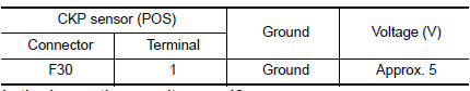
- Check the voltage between CKP sensor (POS) harness connector and ground.
3.CHECK CRANKSHAFT POSITION (CKP) SENSOR (POS) POWER SUPPLY CIRCUIT-II
- Turn ignition switch ON.
- Disconnect ECM harness connector.
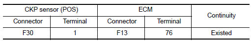
- Check the continuity between CKP sensor (POS) harness connector and ECM harness connector.
4.CHECK SENSOR POWER SUPPLY CIRCUIT
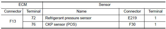
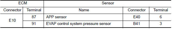
Check harness for short to power and short to ground, between the following terminals.
5.CHECK COMPONENTS
Check the following.
- EVAP control system pressure sensor (Refer to EC-346, "Component Inspection".)
- Refrigerant pressure sensor
6.CHECK APP SENSOR
7.REPLACE ACCELERATOR PEDAL ASSEMBLY
- Replace accelerator pedal assembly
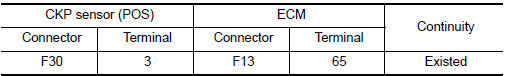
8.CHECK CKP SENSOR (POS) GROUND CIRCUIT FOR OPEN AND SHORT
- Turn ignition switch OFF.
- Disconnect ECM harness connector.
- Check the continuity between CKP sensor (POS) harness connector and ECM harness connector.
- Also check harness for short to ground and short to power.
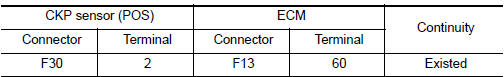
9.CHECK CKP SENSOR (POS) INPUT SIGNAL CIRCUIT FOR OPEN AND SHORT
- Check the continuity between CKP sensor (POS) harness connector and ECM harness connector.
- Also check harness for short to ground and short to power.
10.CHECK CRANKSHAFT POSITION SENSOR (POS)
11.CHECK GEAR TOOTH
Visually check for chipping drive plate gear tooth.
12.CHECK INTERMITTENT INCIDENT
Component Inspection
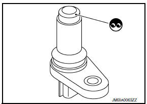
1.CHECK CRANKSHAFT POSITION SENSOR (POS)-I
- Loosen the fixing bolt of the sensor.
- Disconnect crankshaft position sensor (POS) harness connector.
- Remove the sensor.
- Visually check the sensor for chipping.
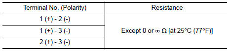
2.CHECK CRANKSHAFT POSITION SENSOR (POS)-II
Check resistance crankshaft position sensor (POS) terminals as per the following.
 P0327, P0328, P0332, P0333 KS
Description
The knock sensor is attached to the cylinder block. It senses engine knocking
using a piezoelectric element. A
knocking vibration from the cylinder block is sensed as vibrational pres ...
 P0340, P0345 CMP sensor (PHASE)
Description
The camshaft position sensor (PHASE) senses the retraction of
camshaft (INT) to identify a particular cylinder. The camshaft position
sensor (PHASE) senses the piston position.
...
Other materials:
Main line between HVAC and A-bag circuit
Diagnosis Procedure
1.CHECK HARNESS CONTINUITY (OPEN CIRCUIT)
Turn the ignition switch OFF.
Disconnect the battery cable from the negative
terminal.
Disconnect the following harness connectors.
A/C auto amp.
Harness connectors M1 and ...
Center speaker
Description
The audio unit sends audio signals to the BOSE speaker amp. The BOSE speaker
amp. amplifies the audio signals before sending them to the center speaker
using the audio signal circuits.
Diagnosis Procedure
1.CONNECTOR CHECK
Check the audio unit, BOSE speaker amp. and speaker conne ...
Readiness for inspection/maintenance (I/M) test
Due to legal requirements in some states and
Canadian Provinces, your vehicle may be required
to be in what is called the "ready condition"
for an Inspection/Maintenance (I/M) test of
the emission control system.
The vehicle is set to the "ready condition" when it
is driven through certain d ...
Nissan Maxima Owners Manual
- Illustrated table of contents
- Safety-Seats, seat belts and supplemental restraint system
- Instruments and controls
- Pre-driving checks and adjustments
- Monitor, climate, audio, phone and voice recognition systems
- Starting and driving
- In case of emergency
- Appearance and care
- Do-it-yourself
- Maintenance and schedules
- Technical and consumer information
Nissan Maxima Service and Repair Manual

0.0056