Nissan Maxima Service and Repair Manual: P0327, P0328, P0332, P0333 KS
Description
The knock sensor is attached to the cylinder block. It senses engine knocking using a piezoelectric element. A knocking vibration from the cylinder block is sensed as vibrational pressure. This pressure is converted into a voltage signal and sent to the ECM.
DTC Logic
DTC DETECTION LOGIC
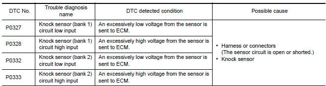
DTC CONFIRMATION PROCEDURE
1.PRECONDITIONING
If DTC Confirmation Procedure has been previously conducted, always perform the following before conducting the next test.
- Turn ignition switch OFF and wait at least 10 seconds.
- Turn ignition switch ON.
- Turn ignition switch OFF and wait at least 10 seconds.
TESTING CONDITION: Before performing the following procedure, confirm that battery voltage is more than 10 V at idle.
2.PERFORM DTC CONFIRMATION PROCEDURE
- Start engine and run it for at least 5 seconds at idle speed.
- Check 1st trip DTC.
Diagnosis Procedure
1.CHECK GROUND CONNECTION
- Turn ignition switch OFF.
- Check ground connection E9.
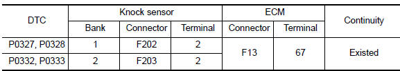
2.CHECK KNOCK SENSOR GROUND CIRCUIT FOR OPEN AND SHORT
- Disconnect knock sensor harness connector and ECM harness connector.
- Check the continuity between knock sensor harness connector and ECM harness connector
- Also check harness for short to ground and short to power.
3.DETECT MALFUNCTIONING PART
Check the following.
- Harness connectors F69, F201
- Harness for open or short between knock sensor and ECM
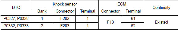
4.CHECK KNOCK SENSOR INPUT SIGNAL CIRCUIT FOR OPEN AND SHORT
- Check the continuity between knock sensor harness connector and ECM harness connector.
- Also check harness for short to ground and short to power
5.DETECT MALFUNCTIONING PART
Check the following.
- Harness connectors F69, F201
- Harness for open or short between knock sensor and ECM
6.CHECK KNOCK SENSOR
7.CHECK INTERMITTENT INCIDENT
Component Inspection
1.CHECK KNOCK SENSOR
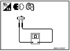
- Turn ignition switch OFF.
- Disconnect knock sensor harness connector.
- Check resistance between knock sensor terminal as per the following. NOTE: It is necessary to use an ohmmeter which can measure more than 10 MΩ.
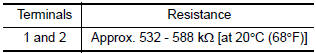
CAUTION: Never use any knock sensors that have been dropped or physically damaged. Use only new ones.
 P0300, P0301, P0302, P0303, P0304, P0305, P0306 misfire
DTC Logic
DTC DETECTION LOGIC
When a misfire occurs, engine speed will fluctuate. If the engine speed
fluctuates enough to cause the crankshaft
position (CKP) sensor (POS) signal to vary, ECM ca ...
 P0335 CKP sensor (POS)
Description
The crankshaft position sensor (POS) is located on the oil pan facing
the gear teeth (cogs) of the signal plate. It detects the fluctuation of
the engine revolution.
The sensor ...
Other materials:
Passenger compartment
WARNING
Never use a fuse of a higher or lower
amperage rating than specified on the
fuse box cover. This could damage the
electrical system or electronic control
units or cause a fire.
If any electrical equipment does not operate,
check for an open fuse.
1. Be sure the ignition switch ...
ECU diagnosis information
POWER STEERING CONTROL UNIT
Reference Value
TERMINA LAYOUT
PHYSICAL VALUES
CAUTION: When using circuit tester or oscilloscope to
measure voltage for inspection, be sure not to extend forcibly any connector
terminals.
Fail Saf
EPS system
EPS system enters the fail-safe mode (that al ...
Driver Attention Alert system operation
If the system detects driver fatigue or that driver
attention is decreasing, the message "Take a
break?"appears in the vehicle information display
and a chime sounds when the vehicle is driven at
speeds above 37 mph (60 km/h).
The system continuously monitors driver attention
and can pro ...
Nissan Maxima Owners Manual
- Illustrated table of contents
- Safety-Seats, seat belts and supplemental restraint system
- Instruments and controls
- Pre-driving checks and adjustments
- Monitor, climate, audio, phone and voice recognition systems
- Starting and driving
- In case of emergency
- Appearance and care
- Do-it-yourself
- Maintenance and schedules
- Technical and consumer information
Nissan Maxima Service and Repair Manual

0.0078