Nissan Maxima Service and Repair Manual: U1000 CAN comm circuit
Description
CAN (Controller Area Network) is a serial communication line for real time application. It is an on-vehicle multiplex communication line with high data communication speed and excellent error detection ability. Many electronic control units are equipped onto a vehicle, and each control unit shares information and links with other control units during operation (not independent). In CAN communication, control units are connected with two communication lines (CAN-H line, CAN-L line) allowing a high rate of information transmission with less wiring.
Each control unit transmits/receives data but selectively reads required data only.
CAN Communication Signal Chart. Refer to LAN-14, "How to Use CAN Communication Signal Chart".
DTC Logic
DTC DETECTION LOGIC
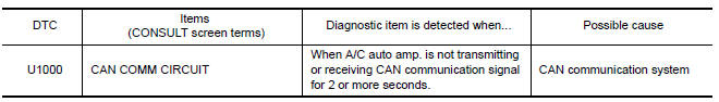
Diagnosis Procedure
1.CHECK WITH SELF-DIAGNOSIS FUNCTION OF CONSULT
- Turn ignition switch ON and wait for 2 or more seconds.
- Using CONSULT, perform "SELF-DIAGNOSIS RESULTS" of HVAC.

 U1010 control unit (CAN)
Description
Initial diagnosis of A/C auto amp.
DTC Logic
DTC DETECTION LOGIC
Diagnosis Procedure
1.CHECK WITH SELF-DIAGNOSIS FUNCTION OF CONSULT
Using CONSULT, perform "SELF-DIAGNOSIS RESULT ...
Other materials:
Door lock function
DOOR LOCK AND UNLOCK SWITCH
DOOR LOCK AND UNLOCK SWITCH : System Diagram
DOOR LOCK AND UNLOCK SWITCH : System Description
DOOR LOCK FUNCTION
Functions Available by Operating the Door Lock and Unlock Switches on
Driver Door and Passenger Door
Interlocked with the locking operation o ...
Diagnosis system (BCM)
COMMON ITEM
COMMON ITEM : CONSULT Function (BCM - COMMON ITEM
APPLICATION ITEM
CONSULT performs the following functions via CAN communication with BCM.
SYSTEM APPLICATION
BCM can perform the following functions.
RETAINED PW
RETAINED PWR : CONSULT Function (BCM - RETAINED PWR)
DATA MONITO ...
Washer level switch
Removal and Installation
REMOVAL
Position the RH front fender protector back. Refer to EXT-24,
"Removal and Installation".
Remove the engine under cover.
Remove the RH front fender protector side cover. Refer to EXT-24,
"Removal and Installation".
Disconnect the front washer level ...
Nissan Maxima Owners Manual
- Illustrated table of contents
- Safety-Seats, seat belts and supplemental restraint system
- Instruments and controls
- Pre-driving checks and adjustments
- Monitor, climate, audio, phone and voice recognition systems
- Starting and driving
- In case of emergency
- Appearance and care
- Do-it-yourself
- Maintenance and schedules
- Technical and consumer information
Nissan Maxima Service and Repair Manual

0.0057