Nissan Maxima Service and Repair Manual: U1010 control unit (CAN)
Description
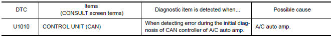
Initial diagnosis of A/C auto amp.
DTC Logic
DTC DETECTION LOGIC
Diagnosis Procedure
1.CHECK WITH SELF-DIAGNOSIS FUNCTION OF CONSULT
Using CONSULT, perform "SELF-DIAGNOSIS RESULTS" of HVAC.
 U1000 CAN comm circuit
Description
CAN (Controller Area Network) is a serial communication line for real time
application. It is an on-vehicle multiplex
communication line with high data communication speed and excellen ...
 B257B, B257C ambient sensor
Description
COMPONENT DESCRIPTION
Ambient Sensor
The ambient sensor (1) is installed to the front bumper
reinforcement.
It detects ambient temperature and converts it into a resistance
va ...
Other materials:
Vehicle jerks during VDC/TCS/ABS control
Diagnosis Procedure
1.SYMPTOM CHECK
Check if the vehicle jerks during VDC/TCS/ABS control.
2.CHECK SELF-DIAGNOSIS RESULTS
Perform self-diagnostic of ABS actuator and electric unit (control unit).
3.CHECK CONNECTOR
Turn ignition switch OFF and disconnect ABS actuator and electric
unit (co ...
Around View Monitor system operation
With the ignition switch in the ON position, move
the shift lever to the R (Reverse) position or press
the CAMERA button to operate the Around
View Monitor.
When the camera is first activated with the bird'seye
view in the display, a red icon (if so equipped)
will flash on the screen. This i ...
Hazard switch
Exploded View
Hazard switch
Cluster lid D
Removal and Installation
REMOVAL
Remove cluster lid D. Refer to IP-18, "Removal and Installation".
Disconnect the harness connector from the hazard switch and
remove.
INSTALLATION
Installation is in the reverse order of removal. ...
Nissan Maxima Owners Manual
- Illustrated table of contents
- Safety-Seats, seat belts and supplemental restraint system
- Instruments and controls
- Pre-driving checks and adjustments
- Monitor, climate, audio, phone and voice recognition systems
- Starting and driving
- In case of emergency
- Appearance and care
- Do-it-yourself
- Maintenance and schedules
- Technical and consumer information
Nissan Maxima Service and Repair Manual

0.0055