
Nissan Maxima Service and Repair Manual: EVAP canister
Removal and Installation (EVAP Canister)
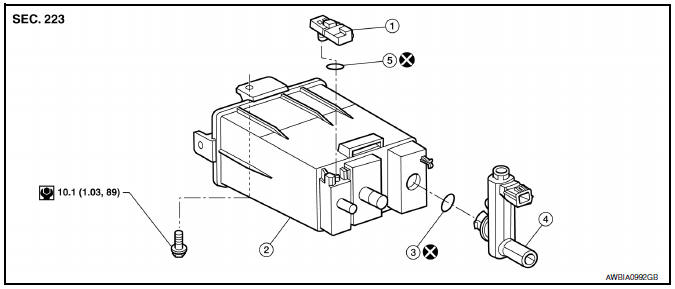
- EVAP control system pressure sensor
- EVAP canister
- O-ring
- EVAP canister vent control valve
- O-ring
NOTE: The EVAP canister vent control valve and EVAP canister system pressure sensor can be removed without removing the EVAP canister.
REMOVAL
- Remove fuel tank. Refer to FL-10, "Removal and Installation".
- Disconnect EVAP hose from EVAP canister.
- Disconnect EVAP control system pressure sensor.
- Disconnect EVAP canister vent control valve and hose.
- Disconnect main EVAP hose from canister.
- Remove EVAP canister.
INSTALLATION
Installation is in the reverse order of removal.
CAUTION: Do not reuse O-rings.
NOTE: Tighten EVAP canister bolt to the specified torque.
Removal and Installation (EVAP Canister Filter)
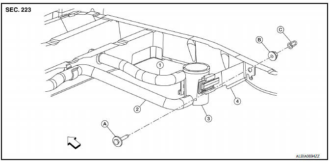
- Canister drain hose
- EVAP hose
- EVAP canister filter
- EVAP filter bracket
- Bolt
- Nut
- Nut
 Front
Front
REMOVAL
- Remove rear stabilizer bar clamps and position rear stabilizer bar aside. Refer to RSU-13, "Removal and Installation".
- Disconnect the EVAP hose from the EVAP canister filter.
- Remove the EVAP filter bracket bolt and position the EVAP filter canister aside.
- Remove the canister drain hose from the EVAP canister filter.
- Remove EVAP canister filter.
INSTALLATION
Installation is in the reverse order of removal.
Inspection
Check EVAP canister as per the following:
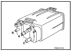
- Block port (B).
- Blow air into port (A) and check that it flows freely out of port (C).
- Release blocked port (B).
- Apply vacuum pressure to port (B) and check that vacuum pressure exists at the ports (A) and (C).
- Block port (A) and (B).
- Apply pressure to port (C) and check that there is no leakage.
 Fuel tank
Exploded View
Fuel filler cap
Grommet
Fuel filler tube
Fuel tank
Fuel filler hose
Fuel tank protector
Fuel tank mounting straps
O-ring
&nb ...
 EVAP canister vent control valve
Removal and Installation
REMOVAL
Remove rear stabilizer bar clamps and position rear stabilizer bar
aside. Refer to RSU-13, "Removal and Installation".
Disconnect breather hose f ...
Other materials:
Emission control system warranty
Your NISSAN vehicle is covered by the following
emission warranties:
For USA
1. Emission Defects Warranty
2. Emissions Performance Warranty
Details of this warranty may be found with other
vehicle warranties in your Warranty Information
Booklet which comes with your NISSAN vehicle.
If you ...
Automatic drive positioner control unit
Removal and Installation
REMOVAL
Remove audio unit. Refer to AV-73, "Removal and Installation"
(BASE AUDIO), AV-161, "Removal and Installation" (BOSE W/MONOCHROME
DISPLAY), AV-481, "Removal and Installation" (BOSE W/ COLOR DISPLAY),
AV-652, "Removal and Installation" (BOSE W/COLOR DISP ...
U0100 lost communication (ECM A)
DTC Logic
DTC DETECTION LOGIC
DTC CONFIRMATION PROCEDURE
1.PREPARATION BEFORE WORK
If another "DTC CONFIRMATION PROCEDURE" occurs just before, turn ignition
switch OFF and wait for at
least 10 seconds, then perform the next test.
2.PERFORM DTC CONFIRMATION PROCEDURE
Start the en ...
Nissan Maxima Owners Manual
- Illustrated table of contents
- Safety-Seats, seat belts and supplemental restraint system
- Instruments and controls
- Pre-driving checks and adjustments
- Monitor, climate, audio, phone and voice recognition systems
- Starting and driving
- In case of emergency
- Appearance and care
- Do-it-yourself
- Maintenance and schedules
- Technical and consumer information
Nissan Maxima Service and Repair Manual

0.0434