Nissan Maxima Service and Repair Manual: Removal and installation
FUEL LEVEL SENSOR UNIT, FUEL FILTER AND FUEL PUMP ASSEMBLY
Exploded View
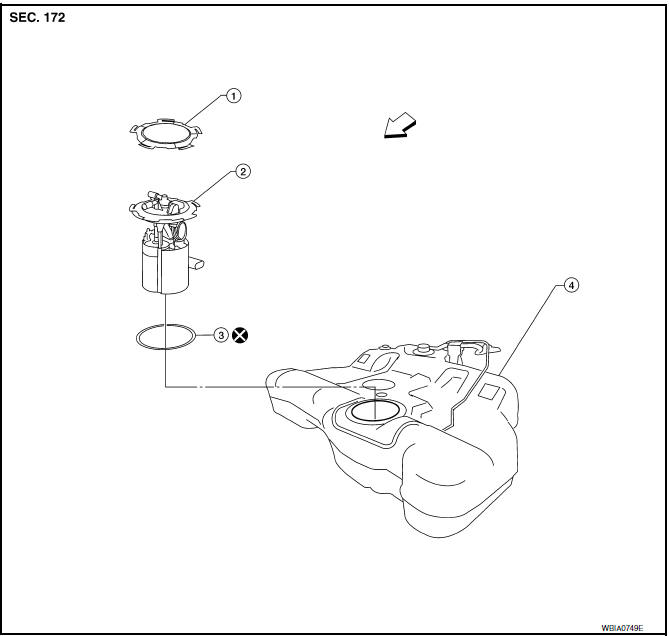
- Lock ring
- Fuel level sensor, fuel filter and fuel pump assembly
- O-ring
- Fuel tank
 Front
Front
Removal and Installation
WARNING: Read "General Precautions" before working on the fuel system. Refer to GI-27, "General Precautions".
NOTE: When removing components such as hoses, tubes/lines, etc., cap or plug openings to prevent fluid from spilling.
REMOVAL
- Unscrew the fuel filler cap to release the pressure inside the fuel tank.
- Release the fuel pressure from the fuel lines. Refer to EC-592, "Inspection".
- Disconnect the battery negative terminal.
- Remove the rear seat cushion. Refer to SE-70, "Removal and Installation" (with fixed seatback, WITH CLIMATE CONTROLLED SEATS), SE-73, "Removal and Installation" (with split seatback, WITH CLIMATE CONTROLLED SEATS), SE-128, "Removal and Installation" (with fixed seatback, W/O CLIMATE CONTROLLED SEATS) SE-131, "Removal and Installation" (with split seatback, W/O CLIMATE CONTROLLED SEATS).
- Turn the four retainers 90 degrees in a clockwise direction and remove the fuel pump inspection hole cover.
- Disconnect the fuel level sensor, fuel filter, and fuel pump assembly harness connector, EVAP hose quick connector, and the fuel feed hose quick connector from the fuel level sensor unit, fuel filter, and fuel pump assembly.
Remove the quick connector as follows:
- Hold the sides of the connector, push in tabs and pull out the tube.
- If the connector and the tube are stuck together, push and pull several times until they start to move. Then disconnect them by pulling.
CAUTION:
- The tube can be removed when the tabs are completely depressed. Do not twist it more than necessary.
- Do not use any tools to remove the quick connector.
- Keep the resin tube away from heat. Be especially careful when welding near the tube.
- Prevent acid liquid such as battery electrolyte, etc. from getting on the resin tube.
- Do not bend or twist the tube during installation and removal.
- Only when the tube is replaced, remove the remaining retainer on the tube or fuel level sensor, fuel filter, and fuel pump assembly.
- When the tube or fuel level sensor, fuel filter, and fuel pump assembly is replaced, also replace the retainer with a new one (green colored retainer).
- To keep the connecting portion clean and to avoid damage and foreign materials, cover them completely with plastic bags or something similar.
- Remove the lock ring using a socket drive handle and Tool as shown.
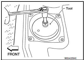
Tool number : KV991J0090 (J-46214) (shown)
: KV101207S0 ( - )
CAUTION: Discard the lock ring if damaged or distorted.
- Remove the fuel level sensor, fuel filter, and fuel pump assembly and O-ring. Discard the O-ring.
CAUTION:
- Do not bend the float arm during removal.
- Do not reuse the O-ring.
INSPECTION AFTER REMOVAL
Inspect the fuel level sensor, fuel filter, and fuel pump for any defects and foreign materials. Replace as necessary.
INSTALLATION
Installation is in the reverse order of removal.
- Install the fuel level sensor, fuel filter, and fuel pump assembly with the fuel feed hose facing the front of the vehicle as shown. Use a new O-ring.
CAUTION: Do not reuse O-ring.
- Connect the quick connector as follows:
- Check the connection for damage or any foreign materials.
- Align the connector with the tube, then insert the connector straight into the tube until a click is heard.
- After the tube is connected, make sure the connection is secure by performing the following checks:
- Pull the tube and the connector to make sure they are securely connected.
- Visually confirm that the two retainer tabs are connected to the quick connector.
INSPECTION AFTER INSTALLATION
Use the following procedure to check for fuel leaks.
- Turn the ignition switch to ON (without starting the engine) to apply fuel pressure to the fuel system, then check the connections for fuel leaks.
- Start the engine and let it idle and check for fuel leaks at the fuel system connections.
 Periodic maintenance
FUEL SYSTEM
Inspection
Inspect fuel lines, fuel filler cap and fuel tank for improper attachment,
leaks, cracks, damage, loose connections, chafing or deterioration.
If
necessary, repair or r ...
 Fuel tank
Exploded View
Fuel filler cap
Grommet
Fuel filler tube
Fuel tank
Fuel filler hose
Fuel tank protector
Fuel tank mounting straps
O-ring
&nb ...
Other materials:
Refrigerant pressure sensor
Description
The refrigerant pressure sensor is installed at the condenser of the air
conditioner system. The sensor uses an
electrostatic volume pressure transducer to convert refrigerant pressure to
voltage. The voltage signal is sent
to ECM, and ECM controls cooling fan system.
Compo ...
P1615 diffrence of key
Description
Performs ID verification through BCM and Intelligent Key
when push-button ignition switch is pressed.
Prohibits the start of engine when an unregistered ID of Intelligent Key is
used.
DTC Logic
DTC DETECTION LOGIC
DTC CONFIRMATION PROCEDURE
1.PERFORM DTC CONFIRMATION PROCED ...
C1105, C1106, C1107, C1108 wheel sensor
DTC Logic
DTC DETECTION LOGIC
DTC CONFIRMATION PROCEDURE
1.CHECK SELF DIAGNOSTIC RESULT
With CONSULT.
Start engine and drive vehicle at approximately 21 km/h (13 MPH)
or more for approximately 5 minutes.
Perform self diagnostic result
Diagnosis Procedure
CAUTION:
Do not check ...
Nissan Maxima Owners Manual
- Illustrated table of contents
- Safety-Seats, seat belts and supplemental restraint system
- Instruments and controls
- Pre-driving checks and adjustments
- Monitor, climate, audio, phone and voice recognition systems
- Starting and driving
- In case of emergency
- Appearance and care
- Do-it-yourself
- Maintenance and schedules
- Technical and consumer information
Nissan Maxima Service and Repair Manual

0.0055