Nissan Maxima Service and Repair Manual: Fuel tank
Exploded View
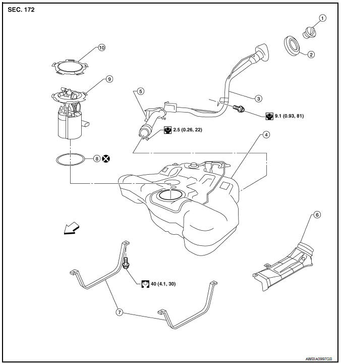
- Fuel filler cap
- Grommet
- Fuel filler tube
- Fuel tank
- Fuel filler hose
- Fuel tank protector
- Fuel tank mounting straps
- O-ring
- Fuel level sensor, fuel filter and fuel pump assembly
- Lock ring
 Front
Front
Removal and Installation
WARNING: Read "General Precautions" before working on the fuel system. Refer to GI-27, "General Precautions".
NOTE: When removing components such as hoses, tubes/lines, etc., cap or plug openings to prevent fluid from spilling.
REMOVAL
- Disconnect the battery negative terminal. Refer to PG-67, "Removal and Installation (Battery)".
- . Open the fuel filler cap to release the pressure inside the fuel tank.
- Release fuel pressure from fuel line. Refer to EC-592, "Inspection".
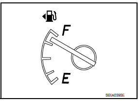
- Check the fuel level with the vehicle on a level surface. If the fuel gauge indicates more than the level as shown (7/8 full), drain the fuel from the fuel tank until the fuel gauge indicates a level at or below as shown (7/8 full).
- In case the fuel pump does not operate, use the following procedure.
- Insert fuel tubing of less than 25mm (0.98in) diameter into the fuel filler tube through the fuel filler opening to drain fuel from the fuel filler tube.
- Disconnect the fuel filler hose from the fuel filler tube.
- Insert fuel tubing into the fuel tank through the fuel filler hose to drain fuel from the fuel tank.
- As a guide, the fuel level reaches or is less than the level on
the fuel gauge as shown, when approximately 10
 (2 5/8 US gal, 2 1/4 Imp gal) of fuel is
drained from a full fuel tank.
(2 5/8 US gal, 2 1/4 Imp gal) of fuel is
drained from a full fuel tank.
- Remove the rear seat cushion. Refer to SE-70, "Removal and Installation" (with fixed seatback, WITH CLIMATE CONTROLLED SEATS), SE-73, "Removal and Installation" (with split seatback, WITH CLIMATE CONTROLLED SEATS), SE-128, "Removal and Installation" (with fixed seatback, W/O CLIMATE CONTROLLED SEATS) SE-131, "Removal and Installation" (with split seatback, W/O CLIMATE CONTROLLED SEATS).
- Turn the four retainers 90 degrees in a clockwise direction and remove the fuel pump inspection hole cover.
- Disconnect the fuel level sensor, fuel filter, and fuel pump assembly harness connector, EVAP hose quick connector, and fuel feed hose quick connector
- Disconnect the quick connectors as follows:
- Hold the sides of the connector, push in tabs and pull out the tube.
- If the connector and the tube are stuck together, push and pull several times until they start to move. Then disconnect them by pulling.
CAUTION:
- The tube can be removed when the tabs are completely depressed. Do not twist it more than necessary.
- Do not use any tools to remove the quick connector.
- Keep the resin tube away from heat. Be especially careful when welding near the tube.
- Prevent acid liquid such as battery electrolyte, from getting on the resin tube.
- Do not bend or twist the tube during installation and removal.
- Only when the tube is replaced, remove the remaining retainer on the tube or fuel level sensor, fuel filter, and fuel pump assembly.
- When the tube or fuel level sensor, fuel filter, and fuel pump assembly is replaced, also replace the retainer with a new one (green colored retainer).
- To keep the connecting portion clean and to avoid damage and foreign materials, cover them completely with plastic bags or something similar.
- Remove the center exhaust tube, with muffler. Refer to EX-5, "Removal and Installation".
- Disconnect the fuel filler hose and recirculation hose at the fuel tank side.
- Disconnect the three parking brake cable mounting brackets on each cable and position the cables out of the way. Refer to PB-6, "Exploded View".
- Remove rear stabilizer bar clamps, then allow stabilizer bar to hang. Refer to RSU-13, "Removal and Installation".
- Remove EVAP canister bolts. Then without disconnecting hoses, position EVAP canister aside. Refer to FL-14, "Removal and Installation (EVAP Canister)".
- Remove the fuel tank protector.
- Remove the fuel tank mounting strap bolts and mounting straps while supporting the fuel tank with a suitable jack.
- Remove the fuel tank.
- If replacing the fuel tank, remove the fuel level sensor unit, fuel filter and fuel pump assembly to transfer to the new fuel tank. Remove and discard the O-ring.
CAUTION: Do not reuse O-ring.
INSTALLATION
Install in the reverse order of removal paying attention to the following.
CAUTION: Do not reuse O-ring.
- Before tightening the fuel tank mounting straps, temporarily
install the filler hose and the recirculation hose.
Tighten all fuel tank mounting strap bolts to specification, then tighten the hose clamps.
- Connect the quick connector as follows:
- Check the connection for damage or any foreign materials.
- Align the connector with the tube, then insert the connector straight into the tube until a click is heard.
- After the tube is connected, make sure the connection is secure by performing the following checks:
- Pull on the tube and the connector to make sure they are securely connected.
- Visually confirm that the two retainer tabs are connected to the quick connector.
INSPECTION AFTER INSTALLATION
Use the following procedure to check for fuel leaks.
- . Turn the ignition switch ON (without starting the engine). Then check the connections for fuel leaks by applying fuel pressure to the fuel piping.
- Run the engine and check for fuel leaks at the fuel system tube and hose connections.
 Removal and installation
FUEL LEVEL SENSOR UNIT, FUEL FILTER AND FUEL PUMP ASSEMBLY
Exploded View
Lock ring
Fuel level sensor, fuel filter and fuel pump assembly
O-ring
Fuel tank Front
Removal a ...
 EVAP canister
Removal and Installation (EVAP Canister)
EVAP control system pressure sensor
EVAP canister
O-ring
EVAP canister vent control valve
O-ring
NOTE: The EVAP canister vent contr ...
Other materials:
Vehicle speed signal circuit
Description
Combination meter sends vehicle speed signal to power steering control unit.
Diagnosis Procedure
1.PERFORM COMBINATION METER SELF-DIAGNOSIS
Perform combination meter self-diagnosis.
2.CHECK HARNESS BETWEEN COMBINATION METER AND POWER STEERING CONTROL UNIT FOR
OPEN
Turn the ...
Preparation
PREPARATION
Special Service Tool
The actual shapes of the tools may differ from those illustrated here.
HFC-134a (R-134a) Service Tool and Equipment
Do not mix HFC-134a (R-134a) refrigerant and/or its specified oil with CFC-12
(R-12) refrigerant and/or its oil.
Separate and non-interchang ...
Around View Monitor system limitations
WARNING
Listed below are the system limitations for
Around View Monitor. Failure to operate
the vehicle in accordance with these system
limitations could result in serious injury
or death.
Do not use the Around View Monitor
with the outside mirrors in the stored
position, and make ...
Nissan Maxima Owners Manual
- Illustrated table of contents
- Safety-Seats, seat belts and supplemental restraint system
- Instruments and controls
- Pre-driving checks and adjustments
- Monitor, climate, audio, phone and voice recognition systems
- Starting and driving
- In case of emergency
- Appearance and care
- Do-it-yourself
- Maintenance and schedules
- Technical and consumer information
Nissan Maxima Service and Repair Manual

0.0063