Nissan Maxima Service and Repair Manual: Rear seat
Exploded View - Fixed Seatback
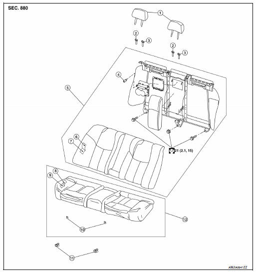
- Headrest
- Headrest holder (free)
- Headrest holder (locked)
- Bumper
- Seatback assembly
- Seatback trim
- Seatback pad
- Seat cushion trim
- Seat cushion pad
- Seat cushion wire cover
- Seat cushion lock
- Seat cushion assembly
Removal and Installation
CAUTION:
When removing and installing, use shop cloths to protect parts from damage.
SEAT CUSHION ASSEMBLY
Removal
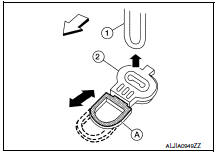
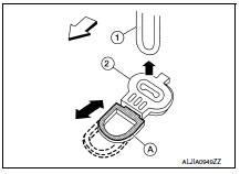
- Locate the seat cushion lock (2) at the front bottom of the seat
cushion assembly (one for each side). Pull the release lever (A)
forward and lift the seat cushion assembly upward to release the
seat cushion wire (1) from the seat cushion lock (2).
 : Front
 - Then pull the seat cushion assembly forward to remove.
Installation
Installation is in the reverse order of removal.
SEATBACK
Removal
- Remove the seat cushion assembly.
- Remove the headrests (LH/RH).
- Remove the seatback assembly bolts and nut.
4. Lift the seatback to disengage seat hook wires from the hangers.
Installation
Installation is in the reverse order of removal.
Exploded View - 60:40 Split Seatback
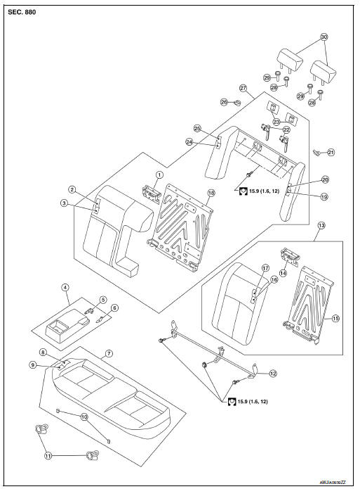
- Seatback latch striker (RH)
- Seatback trim (RH)
- Seatback pad (RH)
- Armrest assembly
- Inner armrest bracket (RH)
- Inner armrest bracket (LH)
- Seat cushion assembly
- Seat cushion trim
- Seat cushion pad
- Seat cushion wire cover
- Seat cushion lock
- Seatback hinge assembly
- Seatback assembly (LH)
- Seatback latch striker (LH)
- Seatback frame (LH)
- Seatback pad (LH)
- Seatback trim (LH)
- Seatback frame (RH)
- Side bolster pad (LH)
- Side bolster trim (LH)
- Seat belt guide (LH)
- Seatback latch assembly
- Seatback latch cover
- Side bolster pad (RH)
- Side bolster trim (RH)
- Seat belt guide (RH)
- Seatback assembly (RH)
- Headrest holder (locked)
- Headrest holder (free)
- Headrest
Removal and Installation
CAUTION:
When removing and installing, use shop cloths to protect parts from damage.
SEAT CUSHION ASSEMBLY
Removal
- Locate the seat cushion lock (2) at the front bottom of the seat
cushion assembly (one for each side). Pull the release lever (A)
forward and lift the seat cushion assembly upward to release the
seat cushion wire (1) from the seat cushion lock (2).
 : Front
 - Then pull the seat cushion assembly forward to remove.
Installation
Installation is in the reverse order of removal.
SEATBACK
Removal
- Lock seatback (LH/RH) in upright position.
- Remove the seatback hinge assembly bolts and nut.
- Fold seatback (LH/RH) forward.
4. Remove seatback latch covers (A).
5. Remove the halo upper frame assembly bolts (B).
6. Remove the seatback assembly.
Installation
Installation is in the reverse order of removal.
 Front seat
Exploded View
DRIVER
Driver Seat - With Climate Controlled Seats
Seatback board
Seatback board clip
Seat cushion lower rear finisher
Seat harness
Seat cushion inner finisher inside ...
 Climate controlled seat blower filter
Removal and Installation
REMOVAL
CAUTION:
When removing and installing, use shop cloths to protect parts
from damage.
Remove front seat. Refer to SE-68, "Removal and Installation".
Turn blo ...
Other materials:
System description
EPS SYSTEM
System Diagram
CONTROL DIAGRAM
System Description
The EPS system controls the power steering solenoid valvethrough the
power steering control unit.
The valve driving voltage to control the power steering solenoid
valve varies according to the vehicle speed.
OPERATION ...
B2634, B2635 air mix door motor (passenger side)
Description
COMPONENT DESCRIPTION
Air Mix Door Motor (Passenger Side)
The air mix door motor (passenger side) (1) is attached to the
heater & cooling unit assembly.
It rotates so that the air mix door is opened or closed to a
position
set by the A/C auto amp.
Motor rotation is t ...
Emission control system warranty
Your NISSAN vehicle is covered by the following
emission warranties:
For USA
1. Emission Defects Warranty
2. Emissions Performance Warranty
Details of this warranty may be found with other
vehicle warranties in your Warranty Information
Booklet which comes with your NISSAN vehicle.
If you ...
Nissan Maxima Owners Manual
- Illustrated table of contents
- Safety-Seats, seat belts and supplemental restraint system
- Instruments and controls
- Pre-driving checks and adjustments
- Monitor, climate, audio, phone and voice recognition systems
- Starting and driving
- In case of emergency
- Appearance and care
- Do-it-yourself
- Maintenance and schedules
- Technical and consumer information
Nissan Maxima Service and Repair Manual

0.0055