Nissan Maxima Service and Repair Manual: Daytime running light system
System Diagram
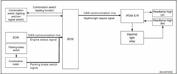
System Description
The headlamp system for Canada vehicles is equipped with a daytime light relay that activates the high beam headlamps at approximately half illumination whenever the engine is running. If the parking brake is depressed before the engine is started, the daytime lights will not be illuminated. The daytime lights will illuminate once the parking brake is released. Thereafter, the daytime lights will continue to operate when the parking brake is depressed.
Component Parts Location
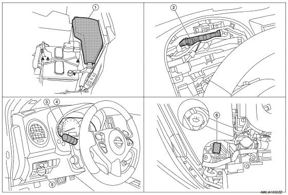
- IPDM E/R E17, E18, E200, E201
- BCM M16,M17, M18, M19 (view with combination meter removed)
- Combination switch (lighting and turn signal switch) M28
- Combination meter M24
- Parking brake switch E35
- Daytime light relay E228
Component Description
After starting the engine with the parking brake released and the lighting switch in the OFF or 1ST position, the headlamp high beam automatically turns on. With the lighting switch in the 2nd position or with autolamps ON, the headlamps function the same as conventional light systems.
OPERATION
The BCM monitors inputs from the parking brake switch and the combination switch (lighting and turn signal switch) to determine when to activate the daytime light system. The BCM sends a daytime light request to the IPDM E/R via the CAN communication lines. The IPDM E/R grounds the daytime light relay which in turn, provides power to the ground side of the RH high beam lamp. Power flows backward through the RH high beam lamp to the IPDM E/R, through the high beam fuses, through the LH high beam lamp circuit to the LH high beam lamp and on to ground. The high beam lamps are wired in series which causes them to illuminate at a reduced intensity.
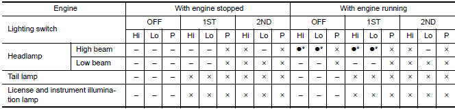
- Hi: "HIGH BEAM" position
- Lo: "LOW BEAM" position
- P: "FLASH TO PASS" position
- ×: Lamp "ON"
- -: Lamp "OFF"
 : Lamp dims. (Added functions)
- *: When starting the engine with the parking brake released, the
daytime lights will operate.
When starting the engine with the parking brake depressed, the daytime lights will not operate.
 Headlamp
System Diagram
System Description
Control of the headlamp system operation is dependent upon the position of
the combination switch (lighting and turn signal switch). When the lighting
switch ...
 Auto light system
System Diagram
System Description
BCM (Body Control Module) controls auto light operation according to
signals from optical sensor, lighting switch and ignition switch.
IPDM E/R (Intellige ...
Other materials:
Satellite radio antenna
Removal and Installation
REMOVAL
Lower the headlining at the rear. Refer to INT-33, "Exploded View".
Disconnect the harness connector (A) from satellite radio
antenna.
Remove the satellite radio antenna nut (B) and the satellite radio
antenna (1).
INSTALLATION
Instal ...
Telescopic switch
Description
ADP steering switch (telescopic switch) is equipped to the steering column.
The operation signal is input to the automatic drive positioner control unit
when the telescopic switch is operated.
Component Function Check
1. CHECK FUNCTION
Select "TELESCO SW-FR", "TELESCO SW-RR" i ...
Warning function symptoms
Symptom Table
WARNING FUNCTION MALFUNCTION
NOTE:
Before performing the diagnosis in the following table, check
"WORK FLOW". Refer to DLK-9, "Work Flow".
Check that vehicle is under the condition shown in "Conditions
of vehicle" before starting diagnosis, and
check each sy ...
Nissan Maxima Owners Manual
- Illustrated table of contents
- Safety-Seats, seat belts and supplemental restraint system
- Instruments and controls
- Pre-driving checks and adjustments
- Monitor, climate, audio, phone and voice recognition systems
- Starting and driving
- In case of emergency
- Appearance and care
- Do-it-yourself
- Maintenance and schedules
- Technical and consumer information
Nissan Maxima Service and Repair Manual

0.0084