
Nissan Maxima Service and Repair Manual: Malfunction indicator lamp
Description
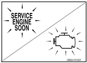
The Malfunction Indicator Lamp (MIL) is located on the combination meter.
The MIL will illuminate when the ignition switch is turned ON without the engine running. This is a bulb check.
When the engine is started, the MIL should turn off. If the MIL remains illuminated, the on board diagnostic system has detected an engine system malfunction.
For details, refer to EC-135, "DIAGNOSIS DESCRIPTION : Malfunction Indicator Lamp (MIL)".
Component Function Check
1.CHECK MIL FUNCTION
- Turn ignition switch ON.
- Check that MIL illuminates.
Diagnosis Procedure
1.CHECK DTC
Check that DTC UXXXX is not displayed.
2.CHECK COMBINATION METER FUNCTION
3.CHECK INTERMITTENT INCIDENT
 Ignition signal
Description
The ignition signal from the ECM is sent to and amplified by the power
transistor. The power transistor turns
ON and OFF the ignition coil primary circuit. This ON/OFF operation induc ...
 On board refueling vapor recovery (ORVR)
Description
From the beginning of refueling, the air and vapor inside the fuel tank go
via the refueling EVAP vapor cut
valve and EVAP/ORVR line to the EVAP canister. The vapor is absorbed by ...
Other materials:
BCM (body control module)
Reference Value
NOTE:
The Signal Tech II Tool (J-50190) can be used to perform the
following functions. Refer to the Signal Tech II
User Guide for additional information.
Activate and display TPMS transmitter IDs
Display tire pressure reported by the TPMS transmitter
Read TPMS DTCs
R ...
Power supply and ground circuit
BCM
BCM : Diagnosis Procedure
1. CHECK FUSE AND FUSIBLE LINK
Check if the following BCM fuses or fusible link are blown.
2. CHECK POWER SUPPLY CIRCUIT
Turn ignition switch OFF.
Disconnect BCM.
Check voltage between BCM harness connector and ground.
3. CHECK GROUND CIRCUIT
Che ...
C1155 BR fluid level low
Description
The brake fluid level switch converts the brake fluid level to an electric
signal and transmits it to the ABS actuator
and electric unit (control unit).
DTC Logic
DTC DETECTION LOGIC
DTC CONFIRMATION PROCEDURE
1.CHECK SELF-DIAGNOSIS RESULTS
Check the self-diagnosis results. ...
Nissan Maxima Owners Manual
- Illustrated table of contents
- Safety-Seats, seat belts and supplemental restraint system
- Instruments and controls
- Pre-driving checks and adjustments
- Monitor, climate, audio, phone and voice recognition systems
- Starting and driving
- In case of emergency
- Appearance and care
- Do-it-yourself
- Maintenance and schedules
- Technical and consumer information
Nissan Maxima Service and Repair Manual

0.0103