
Nissan Maxima Service and Repair Manual: Intelligent key battery
Nissan Maxima Service and Repair Manual / Body exterior, doors, roof & vehicle security / Door & lock / Removal and installation / Intelligent key battery
Removal and Installation
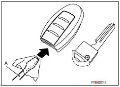
- Release the lock knob at the back of the Intelligent Key and remove the mechanical key.
- Insert a suitable tool (A) wrapped with a cloth into the slit of the corner and twist it to separate the upper part from the lower part.
- Replace the battery with new one.
CAUTION:
- Do not touch the circuit board or battery terminal.
- The key fob is water-resistant. However, if it does get wet, immediately wipe it dry.
Battery replacement :Coin-type lithium battery (CR2032)
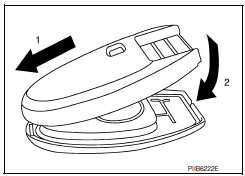
- Align the tips of the upper and lower parts, and then push them together until it is securely closed.
CAUTION:
- When replacing battery, keep dirt, grease, and other foreign materials off the electrode contact area.
- After replacing the battery, check that all Intelligent Key functions work normally.
 Trunk opener request switch
Removal and Installation
REMOVAL
Remove the license lamp finisher (1). Refer to EXL-166, "Removal
and Installation".
Remove the inner bracket screws (A) and inner bracket (2) from ...
 Remote keyless entry receiver
Removal and Installation
REMOVAL
Remove glove box assembly. Refer to IP-20, "Removal and
Installation".
Disconnect the harness connector from the remote keyless
entry receive ...
Other materials:
Mechanical system
Cross-Sectional View
Converter housing
Oil pump
Forward clutch
Reverse brake
Planetary carrier
Primary pulley
Steel belt
Sun gear
Side cover
Internal gear
Secondary pulley
Final gear
D ...
Diagnosis system (BCM)
COMMON ITEM
COMMON ITEM : CONSULT Function (BCM - COMMON ITEM)
APPLICATION ITEM
CONSULT performs the following functions via CAN communication with BCM.
SYSTEM APPLICATION
BCM can perform the following functions.
WIPER
WIPER : CONSULT Function (BCM - WIPER)
DATA MONITOR
ACTIVE TEST
...
Front fog lamp system
Wiring Diagram
...
Nissan Maxima Owners Manual
- Illustrated table of contents
- Safety-Seats, seat belts and supplemental restraint system
- Instruments and controls
- Pre-driving checks and adjustments
- Monitor, climate, audio, phone and voice recognition systems
- Starting and driving
- In case of emergency
- Appearance and care
- Do-it-yourself
- Maintenance and schedules
- Technical and consumer information
Nissan Maxima Service and Repair Manual

© 2017-2026 Copyright www.nimainfo.com
0.0074
0.0074