Nissan Maxima Service and Repair Manual: Headlamp
System Diagram
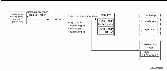
System Description
Control of the headlamp system operation is dependent upon the position of the combination switch (lighting and turn signal switch). When the lighting switch is placed in the 2nd position, the BCM (body control module) receives input requesting the headlamps and park lamps to illuminate. This input is communicated to the IPDM E/R (intelligent power distribution module engine room) across the CAN communication lines. The CPU (central processing unit) of the IPDM E/R controls the headlamp high and headlamp low relay coils. When energized, these relays direct power to the respective headlamps, which then illuminate.
Component Parts Location
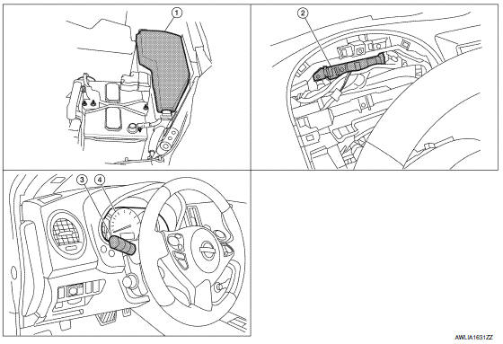
- IPDM E/R E17, E18, E200
- BCM M16, M17, M18, M19 (view with combination meter removed)
- Combination switch (lighting and turn signal switch) M28
- Combination meter M24
Component Description
LOW BEAM OPERATION
When the lighting switch is in 2ND position, the BCM receives input requesting the headlamps to illuminate.
This input is communicated to the IPDM E/R across the CAN communication lines. The CPU of the IPDM E/R controls the headlamp low relay coil which supplies power to the low beam headlamps.
HIGH BEAM OPERATION/FLASH-TO-PASS OPERATION
With the lighting switch in the 2ND position and placed in HIGH position, the BCM receives input requesting the headlamp high beams to illuminate. The flash-to-pass feature can be used any time and also sends a signal to the BCM. This input is communicated to the IPDM E/R across the CAN communication lines. The CPU of the combination meter controls the ON/OFF status off the HIGH BEAM indicator. The CPU of the IPDM E/R controls the headlamp high relay coil which supplies power to the high beam headlamps.
The combination meter receives a high beam request signal (ON) through the CAN communication lines and turns the high beam indicator lamp ON.
EXTERIOR LAMP BATTERY SAVER CONTROL
With the lighting switch (combination switch) in the 2nd position and the ignition switch is turned from ON or ACC to OFF, the battery saver feature is activated.
Under this condition, the headlamps remain illuminated for 5 minutes unless the lighting switch position is changed. If the lighting switch position is changed, then the headlamps are turned off.
This setting can be changed by CONSULT. Refer to EXL-193, "BATTERY SAVER : CONSULT Function (BCM - BATTERY SAVER)".

 Daytime running light system
System Diagram
System Description
The headlamp system for Canada vehicles is equipped with a daytime light
relay that activates the high beam headlamps at approximately half
illumination whene ...
Other materials:
System description
INTELLIGENT KEY SYSTEM/ENGINE START FUNCTION
System Diagram
System Description
INPUT/OUTPUT SIGNAL CHART
SYSTEM DESCRIPTION
The engine start function of Intelligent Key system is a system
that makes it possible to start and stop the
engine without removing the key. It verifies the ...
Vehicle security system
System Diagram
System Description
INPUT/OUTPUT SIGNAL CHART
OPERATION FLOW
SETTING THE VEHICLE SECURITY SYSTEM
Initial Condition
Ignition switch is in OFF position.
Disarmed Phase
When doors or trunk is open, the vehicle
security system is set in the dis ...
Center speaker
Removal and Installation
REMOVAL
Remove the center speaker grille, using a suitable tool.
Remove the center speaker screws (A).
Pull out the center speaker (1), disconnect the harness connector
from the center speaker and remove.
INSTALLATION
Installation is in the reverse order ...
Nissan Maxima Owners Manual
- Illustrated table of contents
- Safety-Seats, seat belts and supplemental restraint system
- Instruments and controls
- Pre-driving checks and adjustments
- Monitor, climate, audio, phone and voice recognition systems
- Starting and driving
- In case of emergency
- Appearance and care
- Do-it-yourself
- Maintenance and schedules
- Technical and consumer information
Nissan Maxima Service and Repair Manual

0.0073