Nissan Maxima Service and Repair Manual: P0507 ISC system
Description
The ECM controls the engine idle speed to a specified level via the fine adjustment of the air, which is let into the intake manifold, by operating the electric throttle control actuator. The operating of the throttle valve is varied to allow for optimum control of the engine idling speed. The crankshaft position sensor (POS) detects the actual engine speed and sends a signal to the ECM.
The ECM controls the electric throttle control actuator so that the engine speed coincides with the target value memorized in the ECM. The target engine speed is the lowest speed at which the engine can operate steadily.
The optimum value stored in the ECM is determined by taking into consideration various engine conditions, such as during warming up, deceleration and engine load (air conditioner, power steering and cooling fan operation, etc.).
DTC Logic
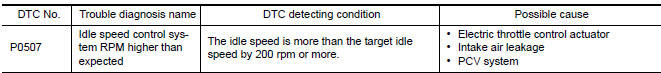
DTC DETECTION LOGIC
NOTE: If DTC P0507 is displayed with other DTC, first perform the trouble diagnosis for the other DTC.
DTC CONFIRMATION PROCEDURE
1.PRECONDITIONING
If DTC Confirmation Procedure has been previously conducted, always perform the following before conducting the next test.
- Turn ignition switch OFF and wait at least 10 seconds.
- Turn ignition switch ON.
- Turn ignition switch OFF and wait at least 10 seconds.
If the target idle speed is out of the specified value, perform EC-21, "IDLE AIR VOLUME LEARNING : Special Repair Requirement", before conducting DTC Confirmation Procedure.
TESTING CONDITION:
- Before performing the following procedure, confirm that battery voltage is more than 11 V at idle.
- Always perform the test at a temperature above −10C(14F).
2.PERFORM DTC CONFIRMATION PROCEDURE
- Start engine and warm it up to normal operating temperature.
- Turn ignition switch OFF and wait at least 10 seconds.
- Turn ignition switch ON.
- Turn ignition switch OFF and wait at least 10 seconds.
- Restart engine and run it for at least 1 minute at idle speed.
- Check 1st trip DTC.
Diagnosis Procedure
1.CHECK PCV HOSE CONNECTION
Confirm that PCV hose is connected correctly.
2.CHECK INTAKE AIR LEAKAGE
- Start engine and let it idle.
- Listen for an intake air leakage after the mass air flow sensor.
3.REPLACE ECM
- Stop engine.
- Replace ECM
 P0506 ISC system
Description
The ECM controls the engine idle speed to a specified level via the fine
adjustment of the air, which is let into
the intake manifold, by operating the electric throttle control actua ...
 P050A, P050e cold start control
Description
ECM controls ignition timing and engine idle speed when engine is started
with pre-warming up condition.
This control promotes the activation of three way catalyst by heating the
c ...
Other materials:
Precaution
PRECAUTIONS
Precaution for Supplemental Restraint System (SRS) "AIR BAG" and "SEAT BELT
PRE-TENSIONER"
with a front seat belt, helps to reduce the risk or severity of injury to the
driver and front passenger for certain
types of collision. This system includes seat belt switch inputs and dua ...
ECU diagnosis information
BCM (BODY CONTROL MODULE)
Reference Value
NOTE: The Signal Tech II Tool (J-50190) can be used
to perform the following functions. Refer to the Signal Tech II User Guide
for additional information.
Activate and display TPMS transmitter IDs
Display tire pressure reported by the ...
Diagnosis system (BCM)
COMMON ITEM
COMMON ITEM : CONSULT Function (BCM - COMMON ITEM)
APPLICATION ITEM
CONSULT performs the following functions via CAN
communication with BCM.
SYSTEM APPLICATION
BCM can perform the following functions.
INTELLIGENT KEY
INTELLIGENT KEY : CONSULT Function (BCM - INTELLIGENT
...
Nissan Maxima Owners Manual
- Illustrated table of contents
- Safety-Seats, seat belts and supplemental restraint system
- Instruments and controls
- Pre-driving checks and adjustments
- Monitor, climate, audio, phone and voice recognition systems
- Starting and driving
- In case of emergency
- Appearance and care
- Do-it-yourself
- Maintenance and schedules
- Technical and consumer information
Nissan Maxima Service and Repair Manual

0.0056