Nissan Maxima Service and Repair Manual: P0506 ISC system
Description
The ECM controls the engine idle speed to a specified level via the fine adjustment of the air, which is let into the intake manifold, by operating the electric throttle control actuator. The operating of the throttle valve is varied to allow for optimum control of the engine idling speed. The crankshaft position sensor (POS) detects the actual engine speed and sends a signal to the ECM.
The ECM controls the electric throttle control actuator so that the engine speed coincides with the target value memorized in the ECM. The target engine speed is the lowest speed at which the engine can operate steadily.
The optimum value stored in the ECM is determined by taking into consideration various engine conditions, such as during warming up, deceleration and engine load (air conditioner, power steering and cooling fan operation, etc.).
DTC Logic
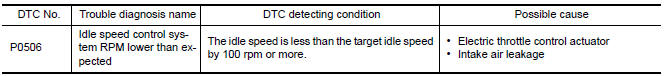
DTC DETECTION LOGIC
NOTE: If DTC P0506 is displayed with other DTC, first perform the trouble diagnosis for the other DTC
DTC CONFIRMATION PROCEDURE
1.PRECONDITIONING
If DTC Confirmation Procedure has been previously conducted, always perform the following before conducting the next test.
- Turn ignition switch OFF and wait at least 10 seconds.
- Turn ignition switch ON.
- Turn ignition switch OFF and wait at least 10 seconds.
If the target idle speed is out of the specified value, perform EC-21, "IDLE AIR VOLUME LEARNING : Special Repair Requirement", before conducting DTC CONFIRMATION PROCEDURE.
TESTING CONDITION:
- Before performing the following procedure, confirm that battery voltage is more than 11 V at idle.
- Always perform the test at a temperature above −10C(14F).
2.PERFORM DTC CONFIRMATION PROCEDURE
- Start engine and warm it up to normal operating temperature.
- Turn ignition switch OFF and wait at least 10 seconds.
- Turn ignition switch ON.
- Turn ignition switch OFF and wait at least 10 seconds.
- Restart engine and run it for at least 1 minute at idle speed.
- Check 1st trip DTC.
Diagnosis Procedure
1.CHECK INTAKE AIR LEAKAGE
- Start engine and let it idle.
- Listen for an intake air leakage after the mass air flow sensor.
2.REPLACE ECM
- Stop engine.
- Replace ECM.
 P0500 VSS
Description
ECM receives vehicle speed signals from two different paths via CAN
communication line: One is from the
ABS actuator and electric unit (control unit) via the combination unit and the ...
 P0507 ISC system
Description
The ECM controls the engine idle speed to a specified level via the fine
adjustment of the air, which is let into
the intake manifold, by operating the electric throttle control actua ...
Other materials:
B2636, B2637, B2638, B2639, B2654, B2655 mode door motor
Description
COMPONENT DESCRIPTION
Mode Door Motor
The mode door motor (1) is attached to the heater & cooling unit
assembly.
It rotates so that air is discharged from the outlet set by the
A/C
auto amp. Motor rotation is conveyed to a link which activates the
mode door.
D ...
Rear door speaker
Removal and Installation
REMOVAL
Remove the rear door finisher. Refer to INT-21, "Removal and
Installation".
Remove the rear door speaker screws (A).
Disconnect the harness connector (B) from the rear door speaker
(1) and remove.
INSTALLATION
Installation is in the reverse order ...
Door lock actuator
DRIVER SIDE
DRIVER SIDE : Description
Locks/unlocks the door with the signal from BCM.
DRIVER SIDE : Component Function Check
1. CHECK FUNCTION
Use CONSULT to perform Active Test ("DOOR LOCK").
Touch "ALL LOCK" or "ALL UNLOCK" to check that it works normally.
DRIVER SIDE : Diagnosis ...
Nissan Maxima Owners Manual
- Illustrated table of contents
- Safety-Seats, seat belts and supplemental restraint system
- Instruments and controls
- Pre-driving checks and adjustments
- Monitor, climate, audio, phone and voice recognition systems
- Starting and driving
- In case of emergency
- Appearance and care
- Do-it-yourself
- Maintenance and schedules
- Technical and consumer information
Nissan Maxima Service and Repair Manual

0.0077