Nissan Maxima Service and Repair Manual: P0500 VSS
Description
ECM receives vehicle speed signals from two different paths via CAN communication line: One is from the ABS actuator and electric unit (control unit) via the combination unit and the other is from TCM.
DTC Logic
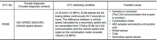
DTC DETECTION LOGIC
NOTE:
- If DTC P0500 is displayed with DTC UXXXX, first perform the trouble diagnosis for DTC UXXXX.
- If DTC P0500 is displayed with DTC P0607, first perform the trouble diagnosis for DTC P0607.
DTC CONFIRMATION PROCEDURE
1.PRECONDITIONING
If DTC CONFIRMATION PROCEDURE has been previously conducted, always perform the following procedure before conducting the next test.
- Turn ignition switch OFF and wait at least 10 seconds.
- Turn ignition switch ON.
- Turn ignition switch OFF and wait at least 10 seconds.
TESTING CONDITION: Before performing the following procedure, confirm that battery voltage is 10 V or more at idle.
2.PERFORM DTC CONFIRMATION PROCEDURE
- Start engine.
- Shift the selector lever to D range and wait at least for 2 seconds.
- Drive the vehicle at least 5 seconds at 20 km/h (13 MPH) or more.
CAUTION: Always drive vehicle at a safe speed.
NOTE: This procedure may be conducted with the drive wheels lifted in the shop or by driving the vehicle. If a road test is expected to be easier, it is unnecessary to lift the vehicle.
- Check 1st trip DTC.
Diagnosis Procedure
1.CHECK DTC WITH TCM
Check DTC with TCM.
2.CHECK DTC WITH ABS ACTUATOR AND ELECTRIC UNIT (CONTROL UNIT)
Check DTC with ABS actuator and electric unit (control unit).
3.CHECK DTC WITH COMBINATION METER
Check DTC with combination meter
4.CHECK SECONDARY SPEED SENSOR
Check secondary speed sensor
5.CHECK WHEEL SENSOR
Check wheel sensor.
 P0462, P0463 fuel level sensor
Description
The fuel level sensor is mounted in the fuel level sensor unit.
The sensor detects a fuel level in the fuel tank and transmits a signal to the
combination meter. The combination
me ...
 P0506 ISC system
Description
The ECM controls the engine idle speed to a specified level via the fine
adjustment of the air, which is let into
the intake manifold, by operating the electric throttle control actua ...
Other materials:
Precaution
Precaution for Supplemental Restraint System (SRS) "AIR BAG" and
"SEAT BELT PRE-TENSIONER"
The Supplemental Restraint System such as "AIR BAG" and "SEAT BELT
PRE-TENSIONER", used along with a front seat belt, helps to reduce the risk
or severity of injury to the driver and front passenger for ...
Normal operating condition
Description
The majority of the audio concerns are the result of outside causes (bad CD,
electromagnetic interference,
etc.).
NOISE
The following noise results from variations in field strength, such as fading
noise and multi-path noise, or
external noise from trains and other sources. I ...
Exit assist function
EXIT ASSIST FUNCTION : System Diagram
EXIT ASSIST FUNCTION : System Description
OUTLINE
When exiting, if the conditions are satisfied, the seat is moved backward
from normal sitting position and the steering column is moved up.
The seat
slide amount at entry/exit operation can be changed ...
Nissan Maxima Owners Manual
- Illustrated table of contents
- Safety-Seats, seat belts and supplemental restraint system
- Instruments and controls
- Pre-driving checks and adjustments
- Monitor, climate, audio, phone and voice recognition systems
- Starting and driving
- In case of emergency
- Appearance and care
- Do-it-yourself
- Maintenance and schedules
- Technical and consumer information
Nissan Maxima Service and Repair Manual

0.008