Nissan Maxima Service and Repair Manual: Inspection and adjustment
Preliminary Check
NOTE: The Signal Tech II Tool (J-50190) can be used to perform the following functions. Refer to the Signal Tech II User Guide for additional information.
- Activate and display TPMS transmitter IDs
- Display tire pressure reported by the TPMS transmitter
- Read TPMS DTCs
- Register TPMS transmitter IDs
1.TIRE PRESSURE
Check all tire pressures.
2.LOW TIRE PRESSURE WARNING LAMP
Check low tire pressure warning lamp activation
3.BCM CONNECTOR
- Disconnect BCM harness connectors.
- Check terminals for damage or loose connection.
- Reconnect harness connector.
4.TRANSMITTER ACTIVATION TOOL
Check battery in transmitter activation tool.
Transmitter Wake Up Operation
NOTE: This procedure must be done after replacement of a TPMS transmitter or BCM. New replacement transmitters are provided "asleep" and must first be "woken up" using Transmitter Activation Tool J-45295 or Signal Tech II Tool J-50190 before ID registration can be performed. Use the following procedure when using the Transmitter Activation Tool J-45295.
NOTE: The Signal Tech II Tool (J-50190) can be used to perform the following functions. Refer to the Signal Tech II User Guide for additional information.
- Activate and display TPMS transmitter IDs
- Display tire pressure reported by the TPMS transmitter
- Read TPMS DTCs
- Register TPMS transmitter IDs
- Turn ignition switch ON. Push the transmitter activation tool against the tire near the front left transmitter. Press the button for 5 seconds. The hazard warning lamps flash per the following diagram.
Tool number : (J-45295)
- Repeat this procedure for each tire in the following order: FL, FR, RR, RL.
- When the BCM finishes assigning each tire ID, the BCM flashes the hazard warning lamps and sends flashing indicator status by CAN according to the following time chart
- After completing wake up of all transmitters, make sure low tire pressure warning lamp goes out.
ID Registration Procedure
NOTE: The Signal Tech II Tool (J-50190) can be used to perform the following functions. Refer to the Signal Tech II User Guide for additional information.
- Activate and display TPMS transmitter IDs
- Display tire pressure reported by the TPMS transmitter
- Read TPMS DTCs
- Register TPMS transmitter IDs
ID REGISTRATION WITH TRANSMITTER ACTIVATION TOOL
NOTE: This procedure must be done after replacement of a TPMS transmitter or BCM. New replacement transmitters are provided "asleep" and must first be "woken up" using Transmitter Activation Tool J-45295 or Signal Tech II Tool J-50190 before ID registration can be performed. Use the following procedure when using the Transmitter Activation Tool J-45295.
- Connect CONSULT.
- Select "ID REGIST" under BCM.
- Push the transmitter activation tool against the tire near the front left transmitter. Press the button for 5 seconds.
Tool number : (J-45295)
- Register the IDs in order from FR LH, FR RH, RR RH and RR LH. When ID registration of each wheel has been completed, the hazard warning lamps flash.
- After completing all ID registrations, press "END" to complete the procedur
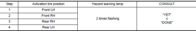
NOTE: Be sure to register all of the IDs in order from FR LH, FR RH, RR RH, to RR LH, or the self-diagnostic results display will not function properly.
ID REGISTRATION WITHOUT TRANSMITTER ACTIVATION TOOL
NOTE: This procedure must be done after replacement of a TPMS transmitter or BCM. New replacement transmitters are provided "asleep" and must first be "woken up" using Transmitter Activation Tool J-45295 or Signal Tech II Tool J-50190 before ID registration can be performed.
- Connect CONSULT.
- Select "ID REGIST" under BCM.
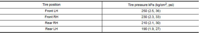
- Adjust the tire pressures to the values shown in the table and drive the vehicle at 40 km/h (25 MPH) or more for a few minutes.
- After completing all ID registrations, press "END" to complete the procedure.
- Inflate all tires to proper pressure.

 Diagnosis and repair workflow
Repair Work Flow
WORK FLOW
DETAILED FLOW
1.CUSTOMER INFORMATION
Interview the customer to obtain detailed information about the symptom.
2.PRELIMINARY CHECK
Perform preliminary check
3.SELF-D ...

Other materials:
DTC/circuit diagnosis
SUNSHADE
Component Parts Location
Rear sunshade unit B22 (View with the rear parcel shelf finisher
removed)
Rear sunshade switch M308
Reference Value
...
Precaution
Precaution for Supplemental Restraint System (SRS) "AIR BAG" and "SEAT
BELT
PRE-TENSIONER"
The Supplemental Restraint System such as "AIR BAG" and "SEAT BELT PRE-TENSIONER",
used along
with a front seat belt, helps to reduce the risk or severity of injury to the
driver ...
Precaution
PRECAUTIONS
Precaution for Supplemental Restraint System (SRS) "AIR BAG" and
"SEAT BELT PRE-TENSIONER"
The Supplemental Restraint System such as "AIR BAG" and "SEAT BELT
PRE-TENSIONER", used along with a front seat belt, helps to reduce the risk
or severity of injury to the driver and front ...
Nissan Maxima Owners Manual
- Illustrated table of contents
- Safety-Seats, seat belts and supplemental restraint system
- Instruments and controls
- Pre-driving checks and adjustments
- Monitor, climate, audio, phone and voice recognition systems
- Starting and driving
- In case of emergency
- Appearance and care
- Do-it-yourself
- Maintenance and schedules
- Technical and consumer information
Nissan Maxima Service and Repair Manual

0.0051