Nissan Maxima Service and Repair Manual: CAN communication circuit
Diagnosis Procedure
1.CONNECTOR INSPECTION
- Turn the ignition switch OFF.
- Disconnect the battery cable from the negative terminal.
- Disconnect all the unit connectors on CAN communication system.
- Check terminals and connectors for damage, bend and loose connection.
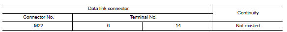
2.CHECK HARNESS CONTINUITY (SHORT CIRCUIT)
Check the continuity between the data link connector terminals.
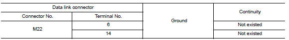
3.CHECK HARNESS CONTINUITY (SHORT CIRCUIT)
Check the continuity between the data link connector and the ground.
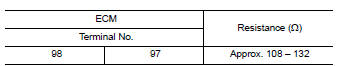
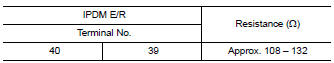
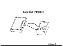
4.CHECK ECM AND IPDM E/R TERMINATION CIRCUIT
- Remove the ECM and the IPDM E/R.
- Check the resistance between the ECM terminals.
3. Check the resistance between the IPDM E/R terminals.
5.CHECK SYMPTOM
Connect all the connectors. Check if the symptoms described in the "Symptom (Results from interview with customer)" are reproduced.
Inspection result
Reproduced>>GO TO 6.
Non-reproduced>>Start the diagnosis again. Follow the trouble diagnosis procedure when past error is detected.
6.CHECK UNIT REPRODUCTION
Perform the reproduction test as per the following procedure for each unit.
- Turn the ignition switch OFF.
- Disconnect the battery cable from the negative terminal.
- Disconnect one of the unit connectors of CAN communication system.
NOTE: ECM and IPDM E/R have a termination circuit. Check other units first.
- Connect the battery cable to the negative terminal. Check if the
symptoms described in the "Symptom
(Results from interview with customer)" are reproduced.
NOTE: Although unit-related error symptoms occur, do not confuse them with other symptoms.
Inspection result
Reproduced>>Connect the connector. Check other units as per the above procedure.
Non-reproduced>>Replace the unit whose connector was disconnected.
 IPDM-E branch line circuit
Diagnosis Procedure
1.CHECK CONNECTOR
Turn the ignition switch OFF.
Disconnect the battery cable from the negative terminal.
Check the terminals and connectors of the IPDM E/R for damage,
...

Other materials:
Power supply and ground circuit
Diagnosis Procedure
1. CHECK FUSES AND FUSIBLE LINK
Check that the following IPDM E/R fuses or fusible link are not blown.
2. CHECK POWER SUPPLY CIRCUIT
Turn ignition switch OFF.
Disconnect IPDM E/R connectors.
Check voltage between IPDM E/R harness connector and ground.
3. CHE ...
Power supply and ground circuit
AUDIO UNIT
AUDIO UNIT : Diagnosis Procedure
1.CHECK FUSES
2.POWER SUPPLY CIRCUIT CHECK
Disconnect audio unit connector M132.
Check voltage between the audio unit connector M132 and ground.
3.GROUND CIRCUIT CHECK
Inspect audio unit case ground.
DISPLAY UNIT
DISPLAY UNIT : Dia ...
Door locks/unlocks precaution
Do not push the door handle request switch
with the Intelligent Key held in your hand as
illustrated. The close distance to the door
handle will cause the Intelligent Key system
to have difficulty recognizing that the Intelligent
Key is outside the vehicle.
After locking with the ...
Nissan Maxima Owners Manual
- Illustrated table of contents
- Safety-Seats, seat belts and supplemental restraint system
- Instruments and controls
- Pre-driving checks and adjustments
- Monitor, climate, audio, phone and voice recognition systems
- Starting and driving
- In case of emergency
- Appearance and care
- Do-it-yourself
- Maintenance and schedules
- Technical and consumer information
Nissan Maxima Service and Repair Manual

0.0073