Nissan Maxima Service and Repair Manual: IPDM-E branch line circuit
Diagnosis Procedure
1.CHECK CONNECTOR
- Turn the ignition switch OFF.
- Disconnect the battery cable from the negative terminal.
- Check the terminals and connectors of the IPDM E/R for damage, bend and loose connection (unit side and connector side).
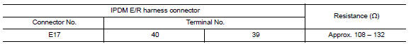
2.CHECK HARNESS FOR OPEN CIRCUIT
- Disconnect the connector of IPDM E/R.
- Check the resistance between the IPDM E/R harness connector terminals.
3.CHECK POWER SUPPLY AND GROUND CIRCUIT
Check the power supply and the ground circuit of the IPDM E/R. Refer to PCS-18, "Diagnosis Procedure".
 TCM branch line circuit
Diagnosis Procedure
1.CHECK CONNECTOR
Turn the ignition switch OFF.
Disconnect the battery cable from the negative terminal.
Check the following terminals and connectors for damage, bend and ...
 CAN communication circuit
Diagnosis Procedure
1.CONNECTOR INSPECTION
Turn the ignition switch OFF.
Disconnect the battery cable from the negative terminal.
Disconnect all the unit connectors on CAN communication syste ...
Other materials:
System malfunction
If the FEB system malfunctions, it will be turned
off automatically, a chime will sound, the FEB
warning light (orange) will illuminate and the
warning message [Malfunction] will appear in the
vehicle information display.
Action to take
If the warning light (orange) comes on, stop the
vehicle ...
Active trace control
The Integrated Dynamics-control Module is an
electric control module that includes the following
functions:
Active Trace Control
Active Engine Brake
Active Ride Control
This system senses driving based on the driver's
steering and acceleration/braking patterns, and
controls brake pres ...
Back-up lamp
Wiring Diagram
...
Nissan Maxima Owners Manual
- Illustrated table of contents
- Safety-Seats, seat belts and supplemental restraint system
- Instruments and controls
- Pre-driving checks and adjustments
- Monitor, climate, audio, phone and voice recognition systems
- Starting and driving
- In case of emergency
- Appearance and care
- Do-it-yourself
- Maintenance and schedules
- Technical and consumer information
Nissan Maxima Service and Repair Manual

0.0059