Nissan Maxima Service and Repair Manual: Power supply and ground circuit
Diagnosis Procedure
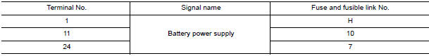
1. CHECK FUSE AND FUSIBLE LINK
Check if the following BCM fuses or fusible link are blown
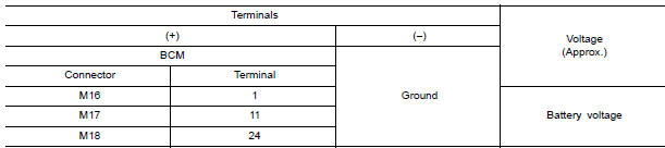
2. CHECK POWER SUPPLY CIRCUIT
- Turn ignition switch OFF.
- Disconnect BCM.
- Check voltage between BCM harness connector and ground.
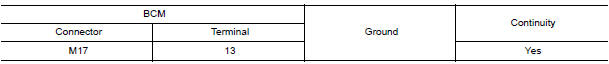
3. CHECK GROUND CIRCUIT
Check continuity between BCM harness connector and ground.
Special Repair Requirement
1. REQUIRED WORK WHEN REPLACING BCM
 B2623 inside key antenna 3
Description
Detects whether Intelligent Key is inside the vehicle.
Installed in the trunk room.
DTC Logic
NOTE:
The Signal Tech II Tool (J-50190) can be used to perform the following
funct ...
 Door switch
Description
Detects door open/close condition.
Component Function Check
1. CHECK FUNCTION
With CONSULT
Check door switches DOOR SW-DR, DOOR SW-AS, DOOR SW-RL, DOOR SW-RR in Data
Monitor mode
...
Other materials:
License plate lamp
Exploded View
License plate lamp
Removal and Installation
LICENSE PLATE LAMP
Removal'
Remove the license lamp finisher. Refer to EXT-31, "Removal and
Installation".
Position trunk lid finisher aside. Refer to INT-36, "Exploded
View".
Remove the license plate lamp screw and ...
Disk eject signal circuit
Description
The eject signal is output to AV control unit when the eject switch of A/C
and AV switch assembly is pressed.
Diagnosis Procedure
1.CHECK CONTINUITY DISK EJECT SIGNAL CIRCUIT
Turn ignition switch OFF.
Disconnect A/C and AV switch assembly connector M98 and AV
control un ...
U1000 CAN comm circuit
Description
CAN (Controller Area Network) is a serial communication line for real time
application. It is an on-vehicle multiplex
communication line with high data communication speed and excellent error
detection ability. Many electronic
control units are equipped onto a vehicle, and each co ...
Nissan Maxima Owners Manual
- Illustrated table of contents
- Safety-Seats, seat belts and supplemental restraint system
- Instruments and controls
- Pre-driving checks and adjustments
- Monitor, climate, audio, phone and voice recognition systems
- Starting and driving
- In case of emergency
- Appearance and care
- Do-it-yourself
- Maintenance and schedules
- Technical and consumer information
Nissan Maxima Service and Repair Manual

0.0053