Nissan Maxima Service and Repair Manual: B2623 inside key antenna 3
Description
Detects whether Intelligent Key is inside the vehicle.
Installed in the trunk room.
DTC Logic
NOTE: The Signal Tech II Tool (J-50190) can be used to perform the following functions. Refer to the Signal Tech II User Guide for additional information.
- Check Intelligent Key relative signal strength
- Confirm vehicle Intelligent Key antenna signal strength
DTC DETECTION LOGIC
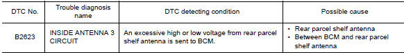
DTC CONFIRMATION PROCEDURE
1. PERFORM DTC CONFIRMATION PROCEDURE
With CONSULT
- Perform rear parcel shelf antenna INSIDE ANT DIAGNOSIS on "Work Support" of "INTELLIGENT KEY".
- Perform "INTELLIGENT KEY" Self Diagnostic Result.
Diagnosis Procedure
NOTE: The Signal Tech II Tool (J-50190) can be used to perform the following functions. Refer to the Signal Tech II User Guide for additional information.
- Check Intelligent Key relative signal strength
- Confirm vehicle Intelligent Key antenna signal strength
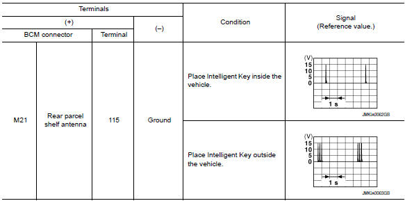
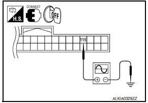
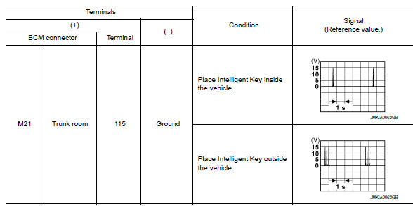
1. CHECK REAR PARCEL SHELF ANTENNA INPUT SIGNAL 1

- Turn ignition switch OFF.
- Check signal between BCM connector and ground with oscilloscope.
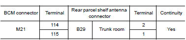
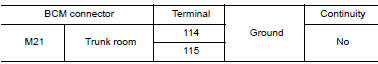
2. CHECK REAR PARCEL SHELF ANTENNA CIRCUIT
- Disconnect BCM and rear parcel shelf antenna connector.
- Check continuity between BCM connector and rear parcel shelf antenna connector.
- Check continuity between BCM connector and ground.
3. CHECK REAR PARCEL SHELF ANTENNA INPUT SIGNAL 2
- Replace rear parcel shelf antenna (new antenna or other antenna).
- Connect BCM and rear parcel shelf antenna connector.
- Check signal between BCM connector and ground with oscilloscope.
 B2622 inside key antenna 2
Description
Detects whether Intelligent Key is inside the vehicle.
Installed under the center console.
DTC Logic
NOTE:
The Signal Tech II Tool (J-50190) can be used to perform the following ...
 Power supply and ground circuit
Diagnosis Procedure
1. CHECK FUSE AND FUSIBLE LINK
Check if the following BCM fuses or fusible link are blown
2. CHECK POWER SUPPLY CIRCUIT
Turn ignition switch OFF.
Disconnect BCM.
C ...
Other materials:
Blower motor control system
System Diagram
System Description
Fan speed is automatically controlled by the temperature setting, ambient
temperature, in-vehicle temperature,
intake temperature, amount of sunload and air mix door position.
By pressing the AUTO switch, the blower motor starts to gradually increase
a ...
Rear lower link & coil spring
Removal and Installation
Removal
Remove the rear wheel and tire using power tool. Refer to WT-60,
"Adjustment".
Loosen the rear lower link adjusting bolt and nut at the rear
suspension member.
Support the rear lower link with a suitable jack.
Support the rear axle housing with a ...
Vehicle security indicator
Description
Vehicle security indicator is built in
combination meter.
NVIS (Nissan Vehicle Immobilizer System-NATS)
and vehicle security system conditions are indicated by
blink or illumination of vehicle security indicator.
Component Function Check
1.CHECK ...
Nissan Maxima Owners Manual
- Illustrated table of contents
- Safety-Seats, seat belts and supplemental restraint system
- Instruments and controls
- Pre-driving checks and adjustments
- Monitor, climate, audio, phone and voice recognition systems
- Starting and driving
- In case of emergency
- Appearance and care
- Do-it-yourself
- Maintenance and schedules
- Technical and consumer information
Nissan Maxima Service and Repair Manual

0.0056