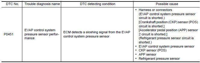
Nissan Maxima Service and Repair Manual: P0451 evap control system pressure sensor
Description
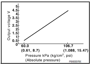
The EVAP control system pressure sensor detects pressure in the purge line. The sensor output voltage to the ECM increases as pressure increases
DTC Logic
DTC DETECTION LOGIC
DTC CONFIRMATION PROCEDURE
NOTE: Never remove fuel filler cap during DTC confirmation procedure.
1.PRECONDITIONING
If DTC Confirmation Procedure has been previously conducted, always perform the following procedure before conducting the next test.
- Turn ignition switch OFF and wait at least 10 seconds.
- Turn ignition switch ON.
- Turn ignition switch OFF and wait at least 10 seconds.
2.PERFORM DTC CONFIRMATION PROCEDURE-1
With CONSULT
- Start engine and let it idle for least 40 seconds. NOTE: Do not depress accelerator pedal even slightly.
- Check 1st trip DTC
3.PERFORM DTC CONFIRMATION PROCEDURE-2
With CONSULT
- Select "EVAP DIAG READY" in "DATA MONITOR" mode of "ENGINE".
- Let it idle until "OFF" of "EVAP DIAG READY" changes to "ON". NOTE: It will take at most 2 hours until "OFF" of "EVAP DIAG READY" changes to "ON".
- Turn ignition switch OFF and wait at least 90 minutes. NOTE: Never turn ignition switch ON during 90 minutes.
- Turn ignition switch ON.
- Select "EVAP LEAK DIAG" in "DATA MONITOR" mode of "ENGINE".
- Check that "EVAP LEAK DIAG" indication.
4.PERFORM DTC CONFIRMATION PROCEDURE-3
With CONSULT
Check 1st trip DTC.
5.PERFORM DTC CONFIRMATION PROCEDURE-4
With GST
- Start engine and let it idle for least 40 seconds. NOTE: Do not depress accelerator pedal even slightly.
- Check 1st trip DTC.
6.PERFORM DTC CONFIRMATION PROCEDURE-5
With GST
- Let it idle for at least 2 hours
- Turn ignition switch OFF and wait at least 90 minutes. NOTE: Never turn ignition switch ON during 90 minutes.
- Turn ignition switch ON.
- Check 1st trip DTC.
Diagnosis Procedure
1.CHECK GROUND CONNECTION
- Turn ignition switch OFF.
- Check ground connection E9.
2.CHECK EVAP CONTROL SYSTEM PRESSURE SENSOR CONNECTOR FOR WATER
- Disconnect EVAP control system pressure sensor harness connector.
- Check that water is not inside connectors.
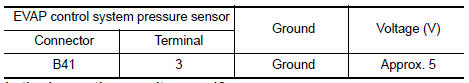
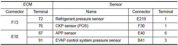
3.CHECK EVAP CONTROL SYSTEM PRESSURE SENSOR POWER SUPPLY CIRCUIT
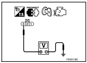
- Turn ignition switch ON.
- Check the voltage between EVAP control system pressure sensor harness connector and ground.
4.CHECK SENSOR POWER SUPPLY CIRCUIT
Check harness for short to power and short to ground, between the following terminals.
5.CHECK COMPONENTS
Check the following.
- Crankshaft position sensor (POS) (Refer to EC-299, "Component Inspection".)
- Refrigerant pressure sensor
6.CHECK APP SENSOR
7.REPLACE ACCELERATOR PEDAL ASSEMBLY
- Replace accelerator pedal assembly.
8.CHECK EVAP CONTROL SYSTEM PRESSURE SENSOR
9.CHECK INTERMITTENT INCIDENT
Component Inspection
1.CHECK EVAP CONTROL SYSTEM PRESSURE SENSOR
- Turn ignition switch OFF.
- Remove EVAP control system pressure sensor with its harness
connector.
Always replace O-ring with a new one.
- Install a vacuum pump to EVAP control system pressure sensor.
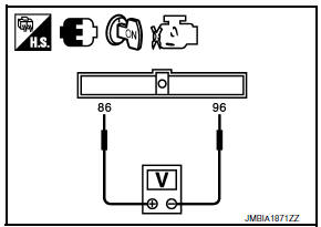
- Turn ignition switch ON and check output voltage between ECM terminals under the following conditions.
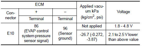
CAUTION:
- Always calibrate the vacuum pump gauge when using it.
- Never apply below -93.3 kPa (-0.952 kg/cm2, -13.53 psi) or pressure over 101.3 kPa (1.033 kg/cm2, 14.69 psi).
 P0448 evap canister vent control valve
Description
The EVAP canister vent control valve is located on the EVAP canister
and is used to seal the canister vent.
This solenoid valve responds to signals from the ECM. When the
ECM s ...
 P0452 evap control system pressure sensor
Description
The EVAP control system pressure sensor detects pressure in the
purge line. The sensor output voltage to the ECM increases as pressure
increases.
DTC Logic
DTC DETECTION LOGIC
...
Other materials:
Precaution
PRECAUTIONS
Precaution for Supplemental Restraint System (SRS) "AIR
BAG" and "SEAT BELT
PRE-TENSIONER"
The Supplemental Restraint System such as "AIR BAG" and
"SEAT BELT PRE-TENSIONER", used along
with a front seat belt, helps to reduce the risk or severity of injury to the
driver and fr ...
Rear power window switch
Description
BCM supplies power.
Rear power window motor operates when rear power window switch is
activated.
Component Function Check
Rear Power Window Switch
1. CHECK REAR POWER WINDOW MOTOR FUNCTION
Check that rear power window motor operates from rear power window switch.
Diagnosi ...
Front passenger air bag module
Removal and Installation
CAUTION:
Before servicing, turn ignition switch OFF, disconnect both
battery terminals and wait at least 3 minutes.
Do not use air tools or electric tools for servicing.
Always work from the side of air bag module. Do not work from
the front of it.
Always pl ...
Nissan Maxima Owners Manual
- Illustrated table of contents
- Safety-Seats, seat belts and supplemental restraint system
- Instruments and controls
- Pre-driving checks and adjustments
- Monitor, climate, audio, phone and voice recognition systems
- Starting and driving
- In case of emergency
- Appearance and care
- Do-it-yourself
- Maintenance and schedules
- Technical and consumer information
Nissan Maxima Service and Repair Manual

0.0057