Nissan Maxima Service and Repair Manual: P0452 evap control system pressure sensor
Description
The EVAP control system pressure sensor detects pressure in the purge line. The sensor output voltage to the ECM increases as pressure increases.
DTC Logic
DTC DETECTION LOGIC
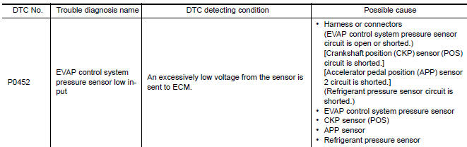
DTC CONFIRMATION PROCEDURE
1.PRECONDITIONING
If DTC Confirmation Procedure has been previously conducted, always perform the following before conducting the next test.
- Turn ignition switch OFF and wait at least 10 seconds.
- Turn ignition switch ON.
- Turn ignition switch OFF and wait at least 10 seconds.
TESTING CONDITION: Always perform test at a temperature of 5C (41F) or more.
2.PERFORM DTC CONFIRMATION PROCEDURE
With CONSULT
- Start engine and warm it up to normal operating temperature.
- Turn ignition switch OFF and wait at least 10 seconds.
- Turn ignition switch ON.
- Turn ignition switch OFF and wait at least 10 seconds.
- Turn ignition switch ON.
- Select "DATA MONITOR" mode with CONSULT.
- Check that "FUEL T/TMP SE" is more than 0C (32F).
- Start engine and wait at least 20 seconds.
- Check 1st trip DTC.
With GST
- Start engine and warm it up to normal operating temperature.
- Set voltmeter probes to ECM harness connector terminals under the following conditions.
- Check that the voltage is less than 4.2 V.
- Turn ignition switch OFF and wait at least 10 seconds.
- Turn ignition switch ON.
- Turn ignition switch OFF and wait at least 10 seconds.
- Start engine and wait at least 20 seconds.
- Check 1st trip DTC.
Diagnosis Procedure
1.CHECK GROUND CONNECTION
- Turn ignition switch OFF.
- Check ground connection E9.
2.CHECK CONNECTOR
- Disconnect EVAP control system pressure sensor harness connector.
- Check that water is not inside connectors.
3.CHECK EVAP CONTROL SYSTEM PRESSURE SENSOR POWER SUPPLY CIRCUIT-I
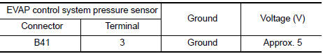
- Turn ignition switch ON.
- Check the voltage between EVAP control system pressure sensor harness connector and ground.
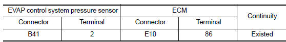
4.CHECK EVAP CONTROL SYSTEM PRESSURE SENSOR POWER SUPPLY CIRCUIT-II
- Turn ignition switch OFF.
- Disconnect ECM harness connector.
- Check the continuity between EVAP control system pressure sensor harness connector and ECM harness connector.
5.DETECT MALFUNCTIONING PART
Check the following.
- Harness connectors B29, E29
- Harness for open or short between EVAP control system pressure sensor and ECM
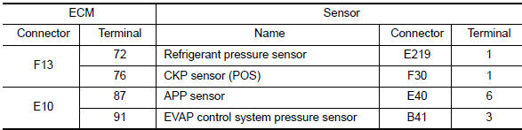
6.CHECK SENSOR POWER SUPPLY CIRCUIT
Check harness for short to power and short to ground, between the following terminals.
7.CHECK COMPONENTS
Check the following.
- Crankshaft position sensor (POS) (Refer to EC-299, "Component Inspection".)
- Refrigerant pressure sensor
8.CHECK APP SENSOR
9.REPLACE ACCELERATOR PEDAL ASSEMBLY
- Replace accelerator pedal assembly.
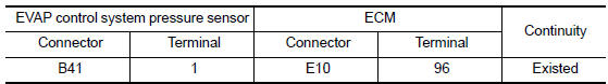
10.CHECK EVAP CONTROL SYSTEM PRESSURE SENSOR GROUND CIRCUIT FOR OPEN AND SHORT
- Turn ignition switch OFF.
- Disconnect ECM harness connector.
- Check the continuity between EVAP control system pressure sensor harness connector and ECM harness connector.
- Also check harness for short to ground and short to power.
11.DETECT MALFUNCTIONING PART
Check the following.
- Harness connectors B10, E29
- Harness for open or short between EVAP control system pressure sensor and ECM
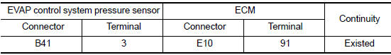
12.CHECK EVAP CONTROL SYSTEM PRESSURE SENSOR INPUT SIGNAL CIRCUIT FOR OPEN AND SHORT
- Check the continuity between EVAP control system pressure sensor harness connector and ECM harness connector
- Also check harness for short to ground and short to power.
13.DETECT MALFUNCTIONING PART
Check the following.
- Harness connectors B10, E29
- Harness for open or short between EVAP control system pressure sensor and ECM
14.CHECK EVAP CONTROL SYSTEM PRESSURE SENSOR
15.CHECK INTERMITTENT INCIDENT
Component Inspection
1.CHECK EVAP CONTROL SYSTEM PRESSURE SENSOR
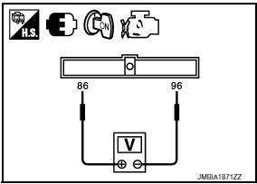
- Turn ignition switch OFF.
- Remove EVAP control system pressure sensor with its harness
connector.
Always replace O-ring with a new one.
- Install a vacuum pump to EVAP control system pressure sensor.
- Turn ignition switch ON and check output voltage between ECM terminals under the following conditions.
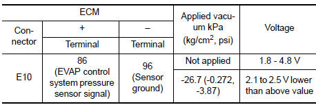
CAUTION:
- Always calibrate the vacuum pump gauge when using it.
- Never apply below -93.3 kPa (-0.952 kg/cm2, -13.53 psi) or pressure over 101.3 kPa (1.033 kg/cm2, 14.69 psi).
 P0451 evap control system pressure sensor
Description
The EVAP control system pressure sensor detects pressure in the
purge line. The sensor output voltage to the ECM increases as pressure
increases
DTC Logic
DTC DETECTION LOGIC
...
 P0453 evap control system pressure sensor
Description
The EVAP control system pressure sensor detects pressure in the
purge line. The sensor output voltage to the ECM increases as pressure
increases.
DTC Logic
DTC DETECTION LOGIC
...
Other materials:
Radiator
Exploded View
Radiator
CVT oil cooler hose
Radiator drain plug
Radiator hose (lower) clamp
Radiator hose (lower)
Radiator hose (lower) bracket
Reservoir tank
Reservoir hose
Radiator cap
Radiator cap adaptor
Radiator hose (upper)
Radiator hose (upper) clamp
&nb ...
Diagnosis system (bluetooth control unit)
Diagnosis Description
The Bluetooth control unit has two diagnostic checks. The first diagnostic
check is performed automatically every ignition cycle during control unit
initialization. The second diagnostic check is performed by the technician
using the steering wheel audio control switches ...
Cooling fan
Description
The ECM controls the cooling fan corresponding to the vehicle speed, engine
coolant temperature, refrigerant
pressure, and air conditioner ON signal. The control system has 4-step control
[HIGH/MIDDLE/LOW/OFF].
COOLING FAN MOTOR
The cooling fan operates at each speed when the cu ...
Nissan Maxima Owners Manual
- Illustrated table of contents
- Safety-Seats, seat belts and supplemental restraint system
- Instruments and controls
- Pre-driving checks and adjustments
- Monitor, climate, audio, phone and voice recognition systems
- Starting and driving
- In case of emergency
- Appearance and care
- Do-it-yourself
- Maintenance and schedules
- Technical and consumer information
Nissan Maxima Service and Repair Manual

0.0065