Nissan Maxima Service and Repair Manual: Cooling fan
Description
The ECM controls the cooling fan corresponding to the vehicle speed, engine coolant temperature, refrigerant pressure, and air conditioner ON signal. The control system has 4-step control [HIGH/MIDDLE/LOW/OFF].
COOLING FAN MOTOR
The cooling fan operates at each speed when the current flows in the cooling fan motor as per the following.
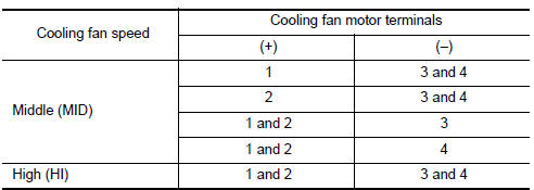
The cooling fan operates at low (LOW) speed when cooling fan motors-1 and -2 are circuited in series under the middle speed condition.
Component Function Ch
1.CHECK COOLING FAN FUNCTION
With CONSULT
- Turn ignition switch ON.
- Perform "COOLING FAN" in "ACTIVE TEST" mode with CONSULT.
- Check that cooling fan speed varies according to the percentage.
Without CONSULT
- Perform IPDM E/R auto active test and check cooling fan motors operation, refer to PCS-11, "Diagnosis Description".
- Check that cooling fan operates.
Diagnosis Procedure
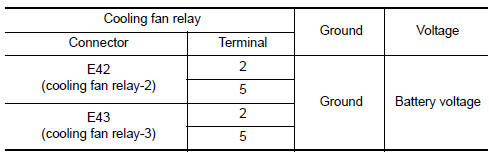
1.CHECK COOLING FAN RELAY POWER SUPPLY CIRCUIT
- Turn ignition switch OFF.
- Disconnect cooling fan relays-2, -3.
- Turn ignition switch ON.
- Check the voltage between cooling fan relays-2, -3 harness connectors and ground.
2.DETECT MALFUNCTIONING PART
Check the following.
- 10 A fuse (No. 33)
- 40 A fusible link (letter K)
- Joint connector-E01 E1
- IPDM E/R harness connector E18
- Junction block connectors E44, E48
- Harness for open or short between cooling fan relay-2 and battery
- Harness for open or short between cooling fan relay-3 and battery
- Harness for open or short between cooling fan relay-2 and IPDM E/R
- Harness for open or short between cooling fan relay-3 and IPDM E/R
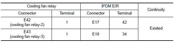
3.CHECK COOLING FAN RELAY OUTPUT SIGNAL CIRCUIT
- Turn ignition switch OFF.
- Disconnect IPDM E/R harness connectors.
- Check the continuity between cooling fan relay-2, -3 harness connectors and IPDM E/R harness connector.
- Also check harness for short to ground and short to power.
4.DETECT MALFUNCTIONING PART
Check the following.
- Harness for open or short between cooling fan relay-2 and IPDM E/R
- Harness for open or short between cooling fan relay-3 and IPDM E/R
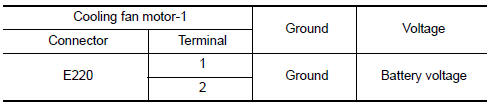
5.CHECK COOLING FAN MOTOR POWER SUPPLY CIRCUIT
- Disconnect cooling fan motor-1 harness connector.
- Check the voltage between cooling fan motor-1 harness connector and ground.
6.DETECT MALFUNCTIONING PART
Check the following.
- 40 A fusible link (letter M)
- Harness connector E12, E203
- Harness for open or short between cooling fan motor-1 and battery
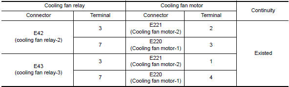
7.CHECK COOLING FAN MOTOR CIRCUIT-I
- Disconnect cooling fan motor-2 harness connector.
- Check the continuity between cooling fan relay-2, -3 harness connectors and cooling fan motor-1, -2 harness connectors.
- Also check harness for short to ground and short to power.
8.DETECT MALFUNCTIONING PART
Check the following.
- Joint connector-E02 E20
- Harness connector E12, E203
- Harness for open or short between cooling fan motor-1 and cooling fan relay-2
- Harness for open or short between cooling fan motor-1 and cooling fan relay-3
- Harness for open or short between cooling fan motor-2 and cooling fan relay-2
- Harness for open or short between cooling fan motor-2 and cooling fan relay-3
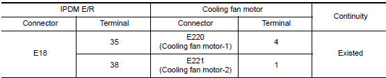
9.CHECK COOLING FAN MOTOR CIRCUIT-II
- Check the continuity between IPDM E/R harness connector and cooling fan motor-1, -2 harness connector.
- Also check harness for short to ground and short to power.
10.DETECT MALFUNCTIONING PART
Check the following.
- Joint connector-E02 E20
- Harness connector E70, E305
- Harness for open or short between cooling fan motor-1 and IPDM E/R
- Harness for open or short between cooling fan motor-2 and IPDM E/R
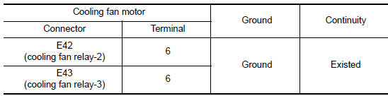
11.CHECK COOLING FAN MOTOR CIRCUIT-III
- Check the continuity between cooling fan relay-2, -3 harness connectors and ground.
- Also check harness for short to ground and short to power.
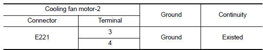
12.CHECK COOLING FAN MOTOR CIRCUIT-IV
- Check the continuity between cooling fan motor-2 harness connector and ground.
- Also check harness for short to ground and short to power.
13.CHECK COOLING FAN RELAYS-2 AND -3
14.CHECK COOLING FAN MOTORS-1 AND -2
15.CHECK INTERMITTENT INCIDENT
Component Inspection (Cooling Fan Motor)
1.CHECK COOLING FAN MOTOR
- Turn ignition switch OFF.
- Disconnect cooling fan motor harness connector.
- Supply cooling fan motor terminals with battery voltage and check operation.
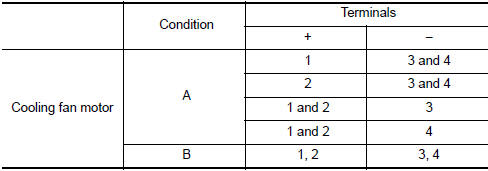
Check that cooling fan speed of condition B is higher than that of A.
Component Inspection (Cooling Fan Relay)
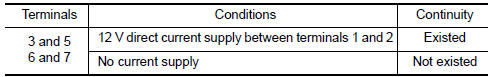
1.CHECK COOLING FAN RELAY
- Disconnect cooling fan relays -2, -3 harness connectors.
- Check continuity between cooling fan relay -2, -3 terminals under the following conditions.
 ASCD indicator
Description
ASCD indicator lamp illuminates to indicate ASCD operation status. CRUISE is
integrated in combination
meter.
CRUISE illuminates when MAIN switch on ASCD steering switch is turned ...
 Check cooling fan relay
Description
The electrical load signal (Headlamp switch signal, rear window defogger
switch signal, etc.) is transferred via
the CAN communication line from BCM to ECM via the IPDM E/R.
Componen ...
Other materials:
Filament
Inspection and Repair
INSPECTION
When measuring voltage, wrap tin foil around the top of the
negative
probe. Then press the foil against the wire with your finger.
Attach probe circuit tester (in Volt range) to middle portion of
each filament.
If a filament is burne ...
Signal buffer system
System Diagram
System Description
OUTLINE
BCM has the signal transmission function that outputs/transmits each
input/received signal to each unit.
Signal transmission function list
Signal name
Input
Output
Description
Ignition switch ON si ...
Diagnosis system (audio unit)
Diagnosis Description
Self-diagnosis mode can perform the following items.
Versions display
Channel check diagnosis
Key check diagnosis
AV communication diagnosis
VERSIONS DISPLAY FUNCTION
Turn ignition switch ON.
Turn the audio unit off.
While pressing "1" button, turn volume ...
Nissan Maxima Owners Manual
- Illustrated table of contents
- Safety-Seats, seat belts and supplemental restraint system
- Instruments and controls
- Pre-driving checks and adjustments
- Monitor, climate, audio, phone and voice recognition systems
- Starting and driving
- In case of emergency
- Appearance and care
- Do-it-yourself
- Maintenance and schedules
- Technical and consumer information
Nissan Maxima Service and Repair Manual

0.0065