Nissan Maxima Service and Repair Manual: Check cooling fan relay
Description
The electrical load signal (Headlamp switch signal, rear window defogger switch signal, etc.) is transferred via the CAN communication line from BCM to ECM via the IPDM E/R.
Component Function Check
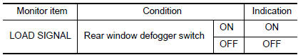
1.CHECK REAR WINDOW DEFOGGER SWITCH FUNCTION
- Turn ignition switch ON.
- Connect CONSULT and select "DATA MONITOR" mode.
- Select "LOAD SIGNAL" and check indication under the following conditions.
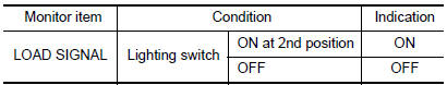
2.CHECK LIGHTING SWITCH FUNCTION
Check "LOAD SIGNAL" indication under the following conditions.
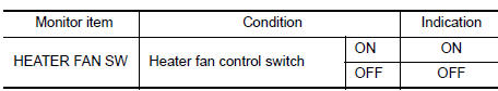
3.CHECK HEATER FAN CONTROL SWITCH FUNCTION
Select "HEATER FAN SW" and check indication under the following conditions.
Diagnosis Procedure
1.INSPECTION START
Confirm the malfunctioning circuit (rear window defogger, headlamp or heater fan).
2.CHECK REAR WINDOW DEFOGGER SYSTEM
3.CHECK HEADLAMP SYSTEM
4.CHECK HEATER FAN CONTROL SYSTEM
 Cooling fan
Description
The ECM controls the cooling fan corresponding to the vehicle speed, engine
coolant temperature, refrigerant
pressure, and air conditioner ON signal. The control system has 4-step con ...
 Electronic controlled engine mount
Description
In the idle range, ECM turns OFF the electronically-controlled engine mount
control solenoid valve and applies
manifold pressure to the electronically controlled engine mount. This de ...
Other materials:
B2632, B2633 air mix door motor (driver side)
Description
COMPONENT DESCRIPTION
Air Mix Door Motor (driver side)
The air mix door motor (driver side) (1) is attached to the heater
&
cooling unit assembly.
It rotates so that the air mix door is opened or closed to a
position
set by the A/C auto amp.
Motor rotation is then ...
Disassembly and assembly
FUEL LEVEL SENSOR UNIT
Disassembly and Assembly
Fuel Level Sensor Unit
Harness connectors
Fuel level sensor unit
Fuel tank temperature sensor
Float arm assembly
Disassembly
NOTE: Before disassembly, note the proper
placement of the wires to the correct terminals a ...
RGB (R: red) signal circuit
Description
Transmit the image displayed with AV control unit with RGB signal to the
display unit.
Diagnosis Procedure
1.CHECK CONTINUITY RGB (R: RED) SIGNAL CIRCUIT
Turn ignition switch OFF.
Disconnect display unit connector M141 and AV control unit
connector M117.
Check continu ...
Nissan Maxima Owners Manual
- Illustrated table of contents
- Safety-Seats, seat belts and supplemental restraint system
- Instruments and controls
- Pre-driving checks and adjustments
- Monitor, climate, audio, phone and voice recognition systems
- Starting and driving
- In case of emergency
- Appearance and care
- Do-it-yourself
- Maintenance and schedules
- Technical and consumer information
Nissan Maxima Service and Repair Manual

0.0073