Nissan Maxima Service and Repair Manual: Electronic controlled engine mount
Description
In the idle range, ECM turns OFF the electronically-controlled engine mount control solenoid valve and applies manifold pressure to the electronically controlled engine mount. This decreases damping force of the electronically- controlled engine mount and absorbs vibrations traveling from the engine to the body for improving the quietness.
In the driving range, ECM turns ON the electronically-controlled engine mount control solenoid valve and cuts manifold pressure applied on the electronically-controlled engine mount. This increases damping force of the electronically-controlled engine mount and reduces vibrations generated during driving.
Component Function Check
1.CHECK OVERALL FUNCTION
With CONSULT
- Start engine and warm it up to normal operating temperature.
- Select "ENGINE MOUNTING" in "ACTIVE TEST" mode with CONSULT and touch "ON/OFF" on the CONSULT screen.
- Check that the motor operating sound is heard from front electronic controlled engine mount and rear electronic controlled engine mount for about 0.5 seconds according to the switching condition of "ENGINE MOUNTING".
Without CONSULT
- Make sure that gear position is P or N.
- Start engine and let it idle.
- Change the engine speed from idle to more than 1,000 rpm and then return to idle (with vehicle stopped).
- Check that the motor operating sound is heard from front
electronic controlled engine mount for and rear
electronic controlled engine mount about 0.5 seconds when changing engine
speed.
It is better to hear the operating sound around the left side front wheel house.
Diagnosis Procedure
1.CHECK VACUUM SOURCE
- Turn ignition switch OFF.
- Reconnect electronic controlled engine mount control solenoid valve harness connector.
- Disconnect vacuum hose connected to electronic controlled engine mount.
- Start engine and let it idle.
- Check vacuum hose for vacuum existence.
Vacuum should exist
2.CHECK VACUUM HOSES AND VACUUM GALLERY
- Turn ignition switch OFF.
- Check vacuum hoses and vacuum gallery for clogging, cracks or improper connection.
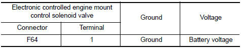
3.CHECK ELECTRONIC CONTROLLED ENGINE MOUNT CONTROL SOLENOID VALVE POWER SUPPLY CIRCUIT
- Disconnect electronic controlled engine mount control solenoid valve harness connector.
- Turn ignition switch ON.
- Check the voltage between front electronic controlled engine mount harness connector and ground.
4.DETECT MALFUNCTIONING PART
Check the following.
- 10 A fuse (No. 3)
- Fuse block (J/B) E6
- Harness connectors E3, F1
- Junction connectors E44, E46
- Harness for open or short between electronic controlled engine mount control solenoid valve and fuse
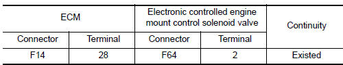
5.CHECK ELECTRONIC CONTROLLED ENGINE MOUNT CONTROL SOLENOID VALVE OUTPUT SIGNAL CIRCUIT FOR OPEN AND SHORT
- Disconnect ECM harness connector.
- Check the continuity between ECM harness connector and electronic controlled engine mount control solenoid valve harness connector.
- Also check harness for short to ground and short to power.
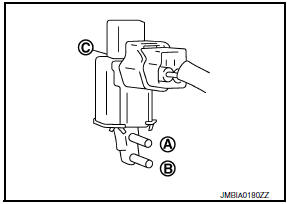
6.CHECK ELECTRONIC CONTROLLED ENGINE MOUNT CONTROL SOLENOID VALVE
7.CHECK ELECTRONIC CONTROLLED ENGINE MOUNT
- Turn ignition switch OFF.
- Install vacuum pump (A) to electronic controlled engine mount (1).
- Check that a vacuum is maintained when applying the vacuum of -40 kPa (-0.41 kg/cm2, -5.8 psi) to electronic controlled engine mount.
- Also visually check electronic controlled engine mount.
8.CHECK INTERMITTENT INCIDENT
Component Inspection
1.CHECK ELECTRONIC CONTROLLED ENGINE MOUNT CONTROL SOLENOID VALVE
With CONSULT
- Turn ignition switch OFF.
- Reconnect electronic controlled engine mount control solenoid valve harness connector.
- Disconnect vacuum hoses connected to electronic controlled engine mount control solenoid valve.
- Turn ignition switch ON.
- Select "ENGINE MOUNTING" in "ACTIVE TEST" mode with CONSULT.
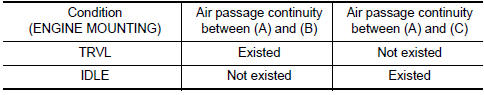
- Check air passage continuity and operation delay time under the following conditions.
Without CONSULT
- Turn ignition switch OFF.
- Disconnect electronic controlled engine mount control solenoid valve harness connector.
- Disconnect vacuum hoses connected to electronic controlled engine mount control solenoid valve.
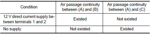
- Check air passage continuity and operation delay time under the following conditions.
 Check cooling fan relay
Description
The electrical load signal (Headlamp switch signal, rear window defogger
switch signal, etc.) is transferred via
the CAN communication line from BCM to ECM via the IPDM E/R.
Componen ...
 Fuel injector
Description
The fuel injector is a small, precise solenoid valve. When the ECM
supplies a ground to the fuel injector circuit, the coil in the fuel injector
is energized. The energized coil p ...
Other materials:
Intermittent incident
Inspection Procedure
INTERMITTENT TROUBLE
An intermittent incident may have occured in the past but is not being
detected currently. This DTC will not bedetected on SELF DIAG [CURRENT], but
may be viewed on SELF DIAG [PAST] using CONSULT.
Trouble Diagnosis with CONSULT
DIAGNOSTIC PROCEDURE 4 ...
Rear seat belt
Exploded View
Seat belt retractor assembly (RH)
Seat belt buckle (RH)
Seat belt buckle center
Seat belt buckle (LH)
Seat belt retractor assembly center
Seat belt retractor assembly (LH)
Retractor anchor bolt
Retractor anti-rotation screw
Lower anchor bolt outer
Se ...
Rear lower link & coil spring
Removal and Installation
Removal
Remove the rear wheel and tire using power tool. Refer to WT-60,
"Adjustment".
Loosen the rear lower link adjusting bolt and nut at the rear
suspension member.
Support the rear lower link with a suitable jack.
Support the rear axle housing with a ...
Nissan Maxima Owners Manual
- Illustrated table of contents
- Safety-Seats, seat belts and supplemental restraint system
- Instruments and controls
- Pre-driving checks and adjustments
- Monitor, climate, audio, phone and voice recognition systems
- Starting and driving
- In case of emergency
- Appearance and care
- Do-it-yourself
- Maintenance and schedules
- Technical and consumer information
Nissan Maxima Service and Repair Manual

0.006