Nissan Maxima Service and Repair Manual: Body control system
System Description
OUTLINE
- ECU DIAGNOSIS INFORMATION controls the various electrical components. It inputs the information required to the control from CAN communication and the signal received from each switch and sensor.
- BCM has combination switch reading function for reading the
operation status of combination switches (light,
turn signal, wiper and washer) in addition to a function for controlling the
operation of various electrical components.
It also has the signal transmission function as the passed point of signal and the power saving control function that reduces the power consumption with the ignition switch OFF.
- BCM is equipped with the diagnosis function that performs the diagnosis with CONSULT and various settings.
CAN communication control
In CAN communication, control units are connected with 2 communication lines (CAN-L, CAN-H) allowing a high rate of information transmission with less wiring. Each control unit transmits/receives the data but selectively reads required information only.
CAN communication signal
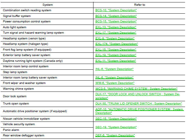
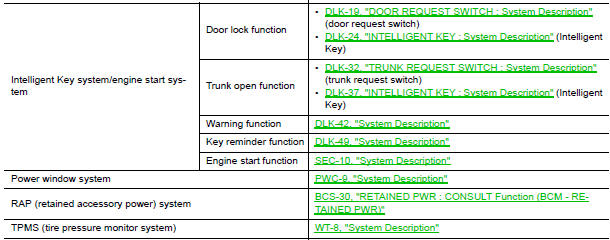
BCM control function list
Component Parts Location
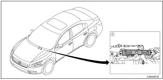
- BCM M16, M17, M18, M19, M20, M21 (view with instrument panel removed)

 Combination switch reading system
System Diagram
System Description
OUTLINE
BCM reads the status of the combination switch (light, turn
signal, wiper and washer) and recognizes the
status of each switch.
BCM has a co ...
Other materials:
ABS function does not operate
Diagnosis Procedure
CAUTION:
ABS does not operate when speed is 10 km/h (6 MPH) or lower.
1.CHECK ABS WARNING LAMP DISPLAY
Make sure that the ABS warning lamp turns OFF after ignition switch is turned
on or when driving
2.CHECK WHEEL SENSOR AND SENSOR ROTOR
Check the following:
Wheel se ...
Vehicle speed signal circuit
Description
Combination meter sends vehicle speed signal to power steering control unit.
Diagnosis Procedure
1.PERFORM COMBINATION METER SELF-DIAGNOSIS
Perform combination meter self-diagnosis.
2.CHECK HARNESS BETWEEN COMBINATION METER AND POWER STEERING CONTROL UNIT FOR
OPEN
Turn the ...
IPDM E/R (intelligent power distribution module engine room)
IPDM E/R (INTELLIGENT POWER DISTRIBUTION MODULE ENGINE
ROOM) : Diagnosis
Procedure
Regarding Wiring Diagram information, refer to PCS-28,
"Wiring Diagram".
1. CHECK FUSES AND FUSIBLE LINK
Check that the following IPDM E/R fuses or fusible link
are not blown.
2. CHECK POWER SUPPLY CIRCU ...
Nissan Maxima Owners Manual
- Illustrated table of contents
- Safety-Seats, seat belts and supplemental restraint system
- Instruments and controls
- Pre-driving checks and adjustments
- Monitor, climate, audio, phone and voice recognition systems
- Starting and driving
- In case of emergency
- Appearance and care
- Do-it-yourself
- Maintenance and schedules
- Technical and consumer information
Nissan Maxima Service and Repair Manual

0.0053