Nissan Maxima Service and Repair Manual: Combination switch reading system
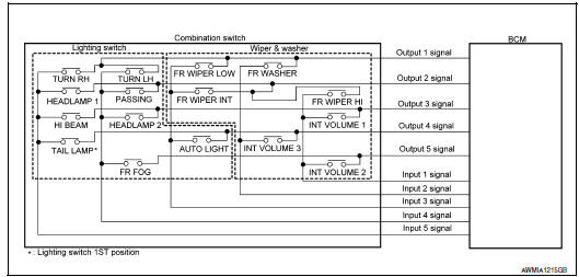
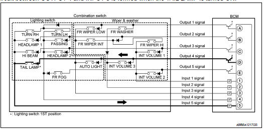
System Diagram
System Description
OUTLINE
- BCM reads the status of the combination switch (light, turn signal, wiper and washer) and recognizes the status of each switch.
- BCM has a combination of 5 output terminals (OUTPUT 1 - 5) and 5 input terminals (INPUT 1 - 5) and reads a maximum of 20 switch states.
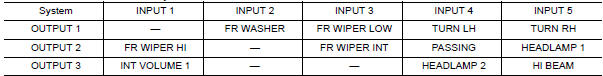
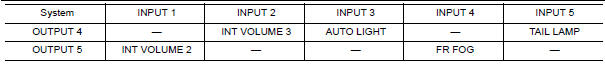
COMBINATION SWITCH MATRIX
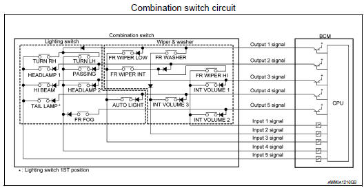
Combination switch INPUT-OUTPUT system list
COMBINATION SWITCH READING FUNCTION
Description
- BCM reads the status of the combination switch at 10ms intervals normally.
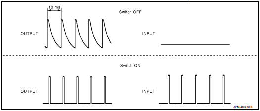
NOTE: BCM reads the status of the combination switch at 60ms intervals when BCM is controlled at low power consumption mode.
- BCM operates as follows and judges the status of the combination switch.
- It operates the transistor on OUTPUT side in the following order: OUTPUT 1 → 2 →3 →4 →5 and outputs voltage waveform.
- The voltage waveform of OUTPUT corresponding to the formed circuit is input into the interface on INPUT side if any (1 or more) switches are ON.
- It reads this change of the voltage as the status signal of the combination switch.
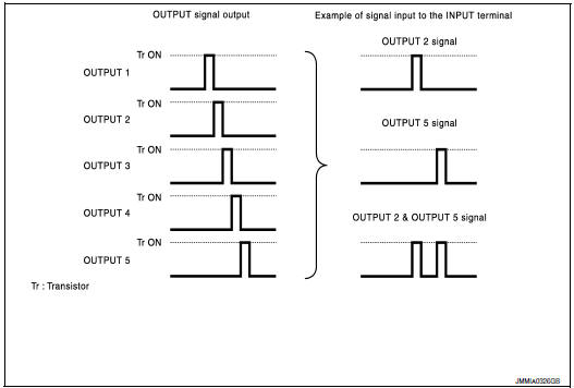
Operation Example
In the following operation example, the combination of the status signals of the combination switch is replaced as follows: INPUT 1 - 5 to "1 - 5" and OUTPUT 1 - 5 to "A - E ".
Example 1: When a switch (TAIL LAMP) is turned ON
- The circuit between OUTPUT 4 and INPUT 5 is formed when the TAIL LAMP is turned ON.
- BCM detects the combination switch status signal "5D" when the signal of OUTPUT 4 is input to INPUT 5.
- BCM judges that the TAIL LAMP switch is ON when the signal "5D" is detected.
Example 2: When some switches (TRUN RH, TAIL LAMP) are turned ON
- The circuits between OUTPUT 1 and INPUT 5 and between OUTPUT 4 and INPUT 5 are formed when the TURN RH switch and TAIL LAMP switch are turned ON.
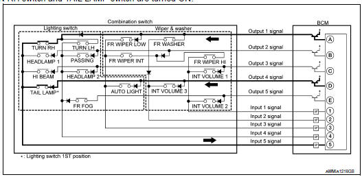
- BCM detects the combination switch status signal "5AD" when the signals of OUTPUT 1 and OUTPUT 4 are input to INPUT 5.
- BCM judges that the TURN RH switch and TAIL LAMP switch are ON when the signal "5AD" is detected.
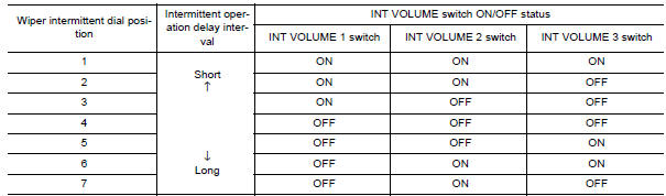
WIPER INTERMITTENT DIAL POSITION SETTING (FRONT WIPER INTERMITTENT OPERATION)
BCM judges the wiper intermittent dial 1 - 7 by the status of INT VOLUME 1, 2, and 3 switches.
 Body control system
System Description
OUTLINE
ECU DIAGNOSIS INFORMATION controls the various electrical
components. It inputs the information required to
the control from CAN communication and the signal rece ...
 Signal buffer system
System Diagram
System Description
OUTLINE
BCM has the signal transmission function that outputs/transmits each
input/received signal to each unit.
Signal transmission function list
...
Other materials:
B2634, B2635 air mix door motor (passenger side)
Description
COMPONENT DESCRIPTION
Air Mix Door Motor (passenger side)
The air mix door motor (passenger side) (1) is attached to the
heater & cooling unit assembly.
It rotates so that the air mix door is opened or closed to a
position
set by the A/C auto amp.
Motor rotation is t ...
B1129 - B1132 side airbag module RH
Description
DTC B1129 - B1132 FRONT RH SIDE AIR BAG MODULE
The front RH side air bag module is wired to the air bag diagnosis sensor
unit. The air bag diagnosis sensorunit will monitor for opens and shorts in
detected lines to the front RH side air bag module.
PART LOCATION
DTC Logic
DTC DE ...
Removal and installation
STARTER MOTOR
Removal and Installation
REMOVAL
Remove the battery tray. Refer to PG-68, "Removal and Installation
(Battery Tray)".
Disconnect the battery cable (A) and starter harness connector.
Remove the starter bolts, then remove the starter
INSTALLATION
Installatio ...
Nissan Maxima Owners Manual
- Illustrated table of contents
- Safety-Seats, seat belts and supplemental restraint system
- Instruments and controls
- Pre-driving checks and adjustments
- Monitor, climate, audio, phone and voice recognition systems
- Starting and driving
- In case of emergency
- Appearance and care
- Do-it-yourself
- Maintenance and schedules
- Technical and consumer information
Nissan Maxima Service and Repair Manual

0.006