Nissan Maxima Service and Repair Manual: Engine maintenance (VQ35DE)
DRIVE BELTS
DRIVE BELTS : Checking Drive Belts
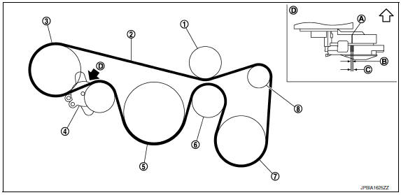
- Idler pulley
- Drive belt
- Power steering oil pump
- Drive belt auto-tensioner
- Crankshaft pulley
- Idler pulley
- A/C compressor
- Generator
- Indicator
- New drive belt range
- Possible use range
- View D
Engine front
WARNING: Inspect and check the drive belts with the engine off.
- Check that the indicator of drive belt auto-tensioner is within the possible use range.
NOTE:
- Check the drive belt auto-tensioner indication when the engine is cold.
- When new drive belt is installed, the indicator should be within the new drive belt range.
- Visually check entire drive belt for wear, damage or cracks.
- If the indicator is out of the possible use range or the drive belt is damaged, replace the drive belt.
DRIVE BELTS : Tension Adjustment
- Belt tension is not manually adjustable, it is automatically adjusted by the drive belt auto-tensioner.
ENGINE COOLANT
ENGINE COOLANT : System Inspection
WARNING:
- Do not remove the radiator cap when the engine is hot. Serious burns could occur from high pressure coolant escaping from the radiator.
- Wrap a thick cloth around the cap. Slowly push down and turn it a quarter turn to allow built-up pressure to escape. Carefully remove the cap by pushing down and turning it all the way.
CHECKING COOLING SYSTEM HOSES
Check hoses for the following:
- Improper attachment
- Leaks
- Cracks
- Damage
- Loose connections
- Chafing
- Deterioration
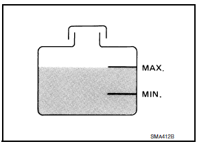
CHECKING RESERVOIR TANK LEVEL
- Check if the reservoir tank coolant level is within MIN to MAX range when the engine is cool.
- Adjust coolant level if it is too much or too little.
ENGINE COOLANT : Changing Engine Coolant
WARNING:
- To avoid being scalded, do not change the coolant when the engine is hot.
- Wrap a thick cloth around cap and carefully remove the cap. First, turn the cap a quarter of a turn to release built-up pressure. Then turn the cap all the way.
DRAINING ENGINE COOLANT
- Remove the engine under cover. Refer to EM-23, "Removal and Installation".
- Open radiator drain plug at the bottom of radiator and remove the radiator filler cap. This is the only step required for a partial cooling system drain. CAUTION: Do not allow the coolant to contact drive belt.
- If removing the heater core, remove the upper heater hose from the engine coolant outlet and apply moderate air pressure of 103.46 kPa (1.055 kg-cm2, 15 psi) maximum for 30 seconds into the hose to blow out excess coolant from the core.
- For a complete cooling system drain, remove the reservoir tank and drain the coolant, and then clean the reservoir tank before installation. CAUTION: Do not allow the coolant to contact drive belt.
- When performing a complete cooling system drain remove the cylinder block front drain plug and the cylinder block RH drain plug.
- Check the drained coolant for contaminants such as rust, corrosion or discoloration.
- If contaminated, flush the engine cooling system.
REFILLING ENGINE COOLANT
- Install the radiator drain plug. If the cooling system was drained completely, install the reservoir tank and the cylinder block drain plugs.
- The radiator must be completely empty of coolant and water.
- Apply sealant to the threads of the cylinder block drain plugs. Use Genuine High Performance Thread Sealant or equivalent.
Radiator drain plug : Refer to CO-14, "Removal and Installation".
Cylinder block front drain plug : 9.8 N*m (1.0 kg-m, 87 in-lb)
Cylinder block RH drain plug : 19.6 N*m (2.0 kg-m, 14 ft-lb)
- If disconnected, reattach the upper radiator hose at the engine side.
- Set the vehicle heater controls to the full HOT and heater ON position. Turn the vehicle ignition ON with the engine OFF as necessary to activate the heater mode.
- Install the Tool by installing the radiator cap adapter onto the radiator neck opening. Then attach the gauge body assembly with the refill tube and the venturi assembly to the radiator cap adapter.
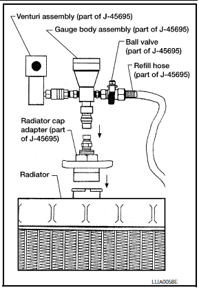
Tool number : KV991J0070 (J-45695)
- Insert the refill hose into the coolant mixture container that is placed at floor level. Make sure the ball valve is in the closed position.
- Use recommended coolant or equivalent.
CAUTION: Do not use any cooling system additives such as radiator sealer. Additives may clog the cooling system and cause damage to the engine, transmission and/or cooling system.
Engine coolant capacity (with reservoir tank) : Refer to MA-15, "FOR USA AND CANADA : Fluids and Lubricants" (United States and Canada) or MA-16, "FOR MEXICO : Fluids and Lubricants" (Mexico).
- Install an air hose to the venturi assembly, the air pressure must be within specification.
Compressed air supply pressure : 549 - 824 kPa (5.6 - 8.4 kg/cm2, 80 - 119 psi)
CAUTION: The compressed air supply must be equipped with an air dryer.
- The vacuum gauge will begin to rise and there will be an audible hissing noise. During this process open the ball valve on the refill hose slightly. Coolant will be visible rising in the refill hose. Once the refill hose is full of coolant, close the ball valve. This will purge any air trapped in the refill hose.
- Continue to draw the vacuum until the gauge reaches 28 inches of vacuum. The gauge may not reach 28 inches in high altitude locations; use the vacuum specifications based on the altitude above sea level.
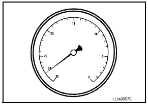
Altitude above sea level Vacuum gauge reading
0 - 100 m (328 ft) : 28 inches of vacuum
300 m (984 ft) : 27 inches of vacuum
500 m (1,641 ft) : 26 inches of vacuum
1,000 m (3,281 ft) : 24 - 25 inches of vacuum
- When the vacuum gauge has reached the specified amount, disconnect the air hose and wait 20 seconds to see if the system loses any vacuum. If the vacuum level drops, perform any necessary repairs to the system and repeat steps 6 - 8 to bring the vacuum to the specified amount. Recheck for any leaks.
- Place the coolant container (with the refill hose inserted) at the
same level as the top of the radiator. Then
open the ball valve on the refill hose so the coolant will be drawn up to
fill the cooling system. The cooling
system is full when the vacuum gauge reads zero.
CAUTION: Do not allow the coolant container to get too low when filling, to avoid air from being drawn into the cooling system.
- Remove the Tool from the radiator neck opening.
- Fill the cooling system reservoir tank to the specified level and install the radiator cap. Run the engine to warm up the cooling system and top up the system as necessary.
- Install the engine under cover.
FUEL LINES
FUEL LINES : Inspection
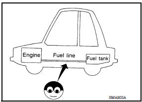
Inspect fuel lines, filler cap and tank for improper attachment, leaks, cracks, damage, loose connections, chafing or deterioration.
If necessary, repair or replace damaged parts.
AIR CLEANER FILTER
AIR CLEANER FILTER : Removal and Installation
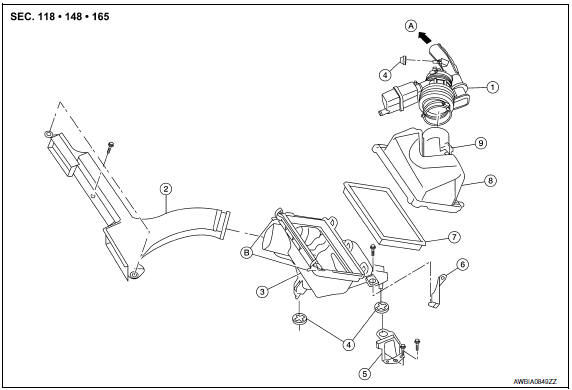
- Air duct hose and resonator assembly
- Front air duct
- Air cleaner case (lower)
- Grommets
- Air cleaner case mounting bracket
- Bracket
- Air cleaner filter
- Air cleaner case (upper)
- Mass air flow sensor
- To electric throttle control actuator
- Air cleaner case side clips
CHANGING THE AIR CLEANER FILTER
NOTE: It is not necessary to remove the front air duct to replace the air cleaner filter.
- Unhook the air cleaner case side clips.
- Remove the air cleaner filter.
- Install a new air cleaner filter.
- Lock the air cleaner case side clips.
ENGINE OIL
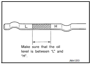
ENGINE OIL : Inspection
OIL LEVEL
NOTE:
- Before starting the engine, check the oil level. If the engine is already started, stop it and allow 10 minutes before checking.
- Check that the oil level is within the range as indicated on the dipstick.
- If it is out of range, add oil as necessary until the dipstick indicates the correct level.
ENGINE OIL : Changing Engine Oil
WARNING:
- Be careful not to burn yourself, as the engine oil may be hot.
- Prolonged and repeated contact with used engine oil may cause skin cancer; try to avoid direct skin contact with used oil. If skin contact is made, wash thoroughly with soap or hand cleaner as soon as possible.
- Position the vehicle so it is level on the hoist.
- Warm up the engine and check for oil leaks from the engine.
- Stop engine and wait for 10 minutes.
- Remove the oil pan drain plug and oil filler cap.
- Drain the engine oil.
- Install the oil pan drain plug with a new washer and refill the engine with new engine oil.
Oil specification and viscosity : Refer to MA-15, "FOR USA AND CANADA :
Engine Oil Recommendation" (United States
and Canada) or MA-17, "FOR MEXICO : Engine
Oil Recommendation" (Mexico).
Oil pan drain plug : 34.3 N*m (3.5 kg-m, 25 ft-lb)
CAUTION:
- Be sure to clean the oil pan drain plug and install with a new washer.
- The refill capacity depends on the oil temperature and drain time. Use the specifications for reference only. Always use the dipstick to determine when the proper amount of oil is in the engine.
- Warm up the engine and check around the oil pan drain plug and oil filter for oil leaks.
- Stop engine and wait for 10 minutes.
- Check the engine oil level using the dipstick.
CAUTION: Do not overfill the engine oil.
OIL FILTER
OIL FILTER : Removal and Installation
REMOVAL
- Drain engine oil.
- Remove front fender protector side cover. Refer to EXT-23, "Exploded View".
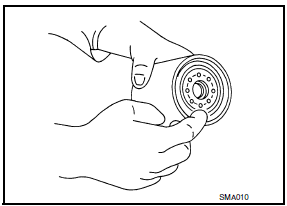
- Remove the oil filter using Tool (A) as shown.
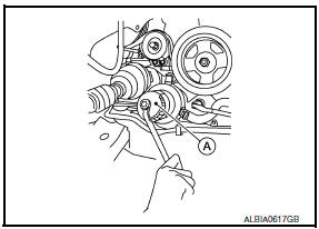
Tool number : KV10115801 (J-38956)
WARNING: Be careful not to get burned; the engine oil may be hot.
CAUTION:
- When removing, prepare a shop cloth to absorb any oil leakage or spillage.
- Do not allow engine oil to adhere to the drive belts.
- Completely wipe off any oil that adheres to the engine and the vehicle.
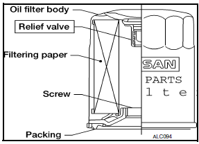
- The oil filter is provided with a relief valve. Use a genuine NISSAN oil filter or equivalent
INSTALLATION
- Remove foreign materials adhering to the oil filter installation surface.
- Apply clean engine oil to the oil seal contact surface of the new oil filter.
- Screw the oil filter manually until it touches the installation surface, then tighten it by turning another 2/3 turn, or tighten to specification using Tool.
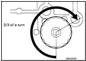
Oil filter : 18.0 N*m (1.8 kg-m, 13 ft-lb)
Tool number : KV10115801 (J-38956)
- Refill the engine with new engine oil. Refer to MA-23, "ENGINE OIL : Changing Engine Oil".
- Check the oil level and add engine oil as necessary. Refer to MA-23, "ENGINE OIL : Inspection".
- After warming up the engine, check for engine oil leaks.
- Install front fender protector side cover. Refer to EXT-23, "Exploded View".
SPARK PLUG
SPARK PLUG : Exploded View
- Ignition coil
- Spark plug
- Rocker cover (RH)
- Rocker cover (LH)
SPARK PLUG : Removal and Installation
REMOVAL
- Remove the ignition coil. Refer to EM-42, "Removal and Installation (LH)" and EM-42, "Removal and Installation (RH)".
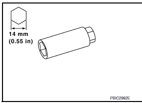
- Remove the spark plug with a suitable spark plug wrench
INSPECTION AFTER REMOVAL
- Do not use a wire brush for cleaning the spark plugs. Replace as necessary.
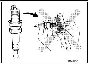
- If plug is covered with carbon, a spark plug cleaner may be used.
Cleaner air pressure : less than 588 kPa (6 kg/cm2, 85 psi)
Cleaning time : less than 20 seconds
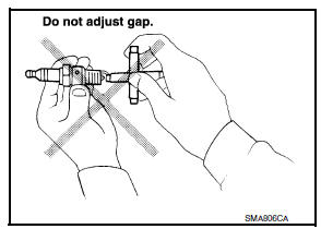
- Checking and adjusting spark plug gap is not required between change intervals. Do not adjust the gap; replace the spark plug as necessary if out of specification.
INSTALLATION
Installation is in the reverse order of removal.
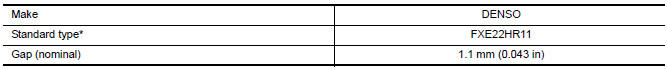
*: Always check with the Parts Department for the latest parts information.
EVAP VAPOR LINES
EVAP VAPOR LINES : Inspection
- Visually inspect EVAP vapor lines for improper attachment and for cracks, damage, loose connections, chafing and deterioration.
- Inspect fuel tank filler cap vacuum relief valve for clogging, sticking, etc.
 Recommended fluids and lubricants
FOR USA AND CANADA
FOR USA AND CANADA : Fluids and Lubricants
*1: For further details, see "Engine Oil Recommendation".
*2: NISSAN recommends Genuine NISSAN Ester Oil available at a NISSAN dea ...
 Chassis and body maintenance
IN-CABIN MICROFILTER
IN-CABIN MICROFILTER : Removal and Installation
REMOVAL
Disengage the filter cover tab (1) by pushing up and pull out to
remove the filter cover.
Remove the in-cabi ...
Other materials:
Tire Pressure Monitoring System (TPMS)
This vehicle is equipped with the TPMS. It monitors
tire pressure of all tires except the spare.
When the low tire pressure warning light is lit and
the "Tire Pressure Low-Add Air" warning appears
in the vehicle information display, one or more of
your tires is significantly under-inflated. I ...
Diagnosis system (bluetooth control unit)
Diagnosis Description
The Bluetooth control unit has two diagnostic checks. The first diagnostic
check is performed automatically every ignition cycle during control unit
initialization. The second diagnostic check is performed by the technician
using the steering wheel audio control switches ...
B2602 shift position
Description
BCM confirms the shift position with the following 2
signals.
CVT selector lever
Speed signal from meter
DTC Logic
DTC DETECTION LOGIC
NOTE:
If DTC B2602 is displayed with DTC
U1000, first perform the trouble diagnosis for DTC U1000. Refer ...
Nissan Maxima Owners Manual
- Illustrated table of contents
- Safety-Seats, seat belts and supplemental restraint system
- Instruments and controls
- Pre-driving checks and adjustments
- Monitor, climate, audio, phone and voice recognition systems
- Starting and driving
- In case of emergency
- Appearance and care
- Do-it-yourself
- Maintenance and schedules
- Technical and consumer information
Nissan Maxima Service and Repair Manual

0.0057