Nissan Maxima Service and Repair Manual: Glove box assembly
Removal and Installation
REMOVAL
- Using a suitable tool, gently remove the instrument panel side finisher (RH).
- Open the glove box door and then remove the glove box assembly screws (A).
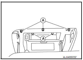
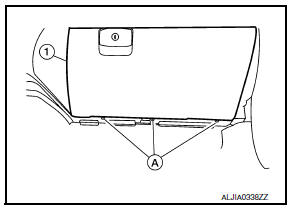
- Remove the glove box assembly lower screws (A).
- Disconnect the harness connectors, then remove the glove box assembly (1).
INSTALLATION
Installation is in the reverse order of removal.
 Instrument lower panel LH
Removal and Installation
REMOVAL
Using a suitable tool, gently remove the instrument side finisher
(LH) (1).
Remove the instrument lower panel (LH) (1).
Open the fuse block cover a ...
 Unit disassembly and assembly
CENTER CONSOLE ASSEMBLY
Exploded View
Center console side finisher (LH)
Center console finisher
CVT finisher
Center console storage bin
Center console screw cover (LH)
Center conso ...
Other materials:
Diagnosis and repair work flow
Work Flow
OVERALL SEQUENCE
DETAILED WORK FLOW
1.CUSTOMER INFORMATION
Get detailed information from the customer about the symptom.
2.PRELIMINARY CHECK
Perform preliminary check.
3.TECHNICAL SERVICE BULLETINS
Check for technical service bulletins.
4.USER MODE
Perform self-diagnosis usin ...
When traveling or registering in another country
When planning to drive your NISSAN vehicle
in another country, you should first find
out if the fuel available is suitable for your vehicle's
engine.
Using fuel with an octane rating that is too low
may cause engine damage. All gasoline vehicles
must be operated with unleaded gasoline. There ...
Shift control system
System Diagram
NOTE: The gear ratio is set for each position separately.
System Description
In order to select the gear ratio that can obtain the driving force in
accordance with driver's intention and the
vehicle condition, TCM monitors the driving conditions, such as the vehicle
speed a ...
Nissan Maxima Owners Manual
- Illustrated table of contents
- Safety-Seats, seat belts and supplemental restraint system
- Instruments and controls
- Pre-driving checks and adjustments
- Monitor, climate, audio, phone and voice recognition systems
- Starting and driving
- In case of emergency
- Appearance and care
- Do-it-yourself
- Maintenance and schedules
- Technical and consumer information
Nissan Maxima Service and Repair Manual

0.0054