Nissan Maxima Service and Repair Manual: ABS actuator and electric unit (control unit)
Exploded View
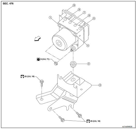
- From master cylinder secondary side
- Grommet
- ABS actuator and electric unit (control unit) bracket
- From master cylinder primary side
- To front LH brake caliper
- To rear RH brake caliper
- To rear LH brake caliper
- To front RH brake caliper
- ABS actuator and electric unit (control
unit)
 Front
Front
Removal and Installation
CAUTION:
- Before removal, disconnect the battery negative terminal.
- To disconnect the brake tubes, use a flare nut wrench to prevent the flare nuts and brake tubes from being damaged. To connect the brake tubes, use a flare nut torque wrench to tighten to the specified torque.
- Do not drop the ABS actuator and electric unit (control unit).
- Do not remove and install the ABS actuator and electric unit (control unit) by holding it by the harness.
- After installation, bleed the air from the brake lines. Refer to BR-16, "Bleeding Brake System".
NOTE:
When removing components such as hoses, tubes/lines, etc., cap or plug openings to prevent fluid from spilling.
REMOVAL
- Disconnect the battery negative terminal. Refer to PG-67, "Removal and Installation (Battery)".
- Remove the front wiper arms. Refer to WW-78, "FRONT WIPER ARMS : Removal and Installation".
- Remove the cowl top and RH cowl top extension. Refer to EXT-21, "Removal and Installation".
- Disconnect the wiper washer hose.
- Remove the strut tower bar. Refer to FSU-13, "Exploded View".
- Disconnect the ABS actuator and electric unit (control unit) connector.
- Loosen the brake tube flare nuts, then disconnect the brake tubes from the ABS actuator and electric unit (control unit).
- Remove the ABS actuator and electric unit (control unit) nuts.
- Remove the ABS actuator and electric unit (control unit).
- Remove the ABS actuator and electric unit (control unit) bracket as necessary.
INSTALLATION
Installation is in the reverse order of removal.
- Bleed brake system, check and adjust brake fluid level as necessary.
CAUTION: Perform the neutral position adjustment for the steering angle sensor
 Sensor rotor
Removal and Installation - Front Sensor Rotor
The front wheel sensor rotor is an integral part of the wheel hub and bearing
assembly and cannot be disassembled.
Removal and Installation - Rear Sen ...
 Yaw rate/side/decel G sensor
Exploded View
Yaw rate/side/decel G sensor
Yaw rate/side/decel G sensor harness
connector
Front
Removal and Installation
CAUTION:
Do not drop or strike the yaw rate/sid ...
Other materials:
B2099 ignition relay off stuck
DTC Logic
DTC DETECTION LOGIC
DTC CONFIRMATION PROCEDURE
1.PERFORM DTC CONFIRMATION PROCEDURE
Turn the power supply position to start under the following
conditions and wait for at least 1 second.
CVT selector lever is in the P (Park) or N (Neutral) position.
Depress the brake ...
Lifting sensor (front)
Description
The lifting sensor (front) is installed to the seat frame.
The pulse signal is input to the driver seat control unit when the
lifting (front) is operated.
The driver seat control unit counts the pulse and calculates the lifting
(front) amount of the seat.
Component Funct ...
EVAP canister
Removal and Installation (EVAP Canister)
EVAP control system pressure sensor
EVAP canister
O-ring
EVAP canister vent control valve
O-ring
NOTE: The EVAP canister vent control valve
and EVAP canister system pressure sensor can be removed without removing the
EVAP canis ...
Nissan Maxima Owners Manual
- Illustrated table of contents
- Safety-Seats, seat belts and supplemental restraint system
- Instruments and controls
- Pre-driving checks and adjustments
- Monitor, climate, audio, phone and voice recognition systems
- Starting and driving
- In case of emergency
- Appearance and care
- Do-it-yourself
- Maintenance and schedules
- Technical and consumer information
Nissan Maxima Service and Repair Manual

0.0065