Nissan Maxima Service and Repair Manual: DLC branch line circuit
Diagnosis Procedure
1.CHECK CONNECTOR
- Turn the ignition switch OFF.
- Disconnect the battery cable from the negative terminal.
- Check the terminals and connectors of the data link connector for damage, bend and loose connection (connector side and harness side).
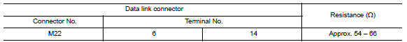
2.CHECK HARNESS FOR OPEN CIRCUIT
Check the resistance between the data link connector terminals.
 BCM branch line circuit
Diagnosis Procedure
1.CHECK CONNECTOR
Turn the ignition switch OFF.
Disconnect the battery cable from the negative terminal.
Check the terminals and connectors of the BCM for damage, bend and ...
 M&A branch line circuit
Diagnosis Procedure
1.CHECK CONNECTOR
Turn the ignition switch OFF.
Disconnect the battery cable from the negative terminal.
Check the terminals and connectors of the combination meter for
...
Other materials:
Center speaker
Removal and Installation
REMOVAL
Remove the center speaker grille, using a suitable tool.
Remove the center speaker screws (A).
Pull out the center speaker (1), disconnect the harness connector
from the center speaker and remove.
INSTALLATION
Installation is in the reverse order ...
Satellite radio antenna
Removal and Installation
REMOVAL
Lower the headlining at the rear. Refer to INT-33, "Exploded
View".
Disconnect the harness connector (A) from satellite radio
antenna.
Remove the satellite radio antenna nut (B) and the satellite radio
antenna (1).
INSTALLATION
Installation is ...
Adjusting the screen
1. Touch the touch-screen display with the
Around View Monitor on.
2. Touch the "Brightness," "Contrast," "Tint,"
"Color," or "Black Level" key.
3. Adjust the item by touching the + or - key
on the touch-screen display.
NOTE:
Do not adjust any of the display settings of
the Around Vi ...
Nissan Maxima Owners Manual
- Illustrated table of contents
- Safety-Seats, seat belts and supplemental restraint system
- Instruments and controls
- Pre-driving checks and adjustments
- Monitor, climate, audio, phone and voice recognition systems
- Starting and driving
- In case of emergency
- Appearance and care
- Do-it-yourself
- Maintenance and schedules
- Technical and consumer information
Nissan Maxima Service and Repair Manual

0.0057