Nissan Maxima Service and Repair Manual: M&A branch line circuit
Diagnosis Procedure
1.CHECK CONNECTOR
- Turn the ignition switch OFF.
- Disconnect the battery cable from the negative terminal.
- Check the terminals and connectors of the combination meter for damage, bend and loose connection (unit side and connector side).
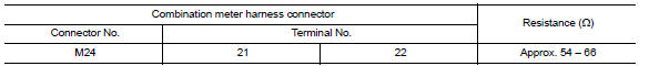
2.CHECK HARNESS FOR OPEN CIRCUIT
- Disconnect the connector of combination meter.
- Check the resistance between the combination meter harness connector terminals.
3.CHECK POWER SUPPLY AND GROUND CIRCUIT
Check the power supply and the ground circuit of the combination meter. Refer to MWI-37, "COMBINATION METER : Diagnosis Procedure".
 DLC branch line circuit
Diagnosis Procedure
1.CHECK CONNECTOR
Turn the ignition switch OFF.
Disconnect the battery cable from the negative terminal.
Check the terminals and connectors of the data link connector for ...
 HVAC branch line circuit
Diagnosis Procedure
1.CHECK CONNECTOR
Turn the ignition switch OFF.
Disconnect the battery cable from the negative terminal.
Check the terminals and connectors of the A/C auto amp. for
dam ...
Other materials:
Automatic door locks
System Diagram
System Description
DOOR LOCK FUNCTION
The door lock and unlock switch (driver side) is build into power
window main switch.
The door lock and unlock switch (passenger side) is on door trim.
Interlocked with the locking operation of door lock and unlock
switch ...
v DLC and HVAC circuit
Diagnosis Procedure
1.CHECK HARNESS CONTINUITY (OPEN CIRCUIT)
Turn the ignition switch OFF.
Disconnect the battery cable from the negative terminal.
Disconnect the following harness connectors.
ECM
A/C auto amp.
Check the continuity between the data link connector and the A/C ...
System description
COMPRESSOR CONTROL FUNCTION
Description
PRINCIPLE OF OPERATION
Compressor is not activated.
Functional circuit diagram
CAN (1): A/C switch signal
: Blower fan motor switch signal
CAN (2): A/C compressor request signal
Functional initial inspection chart
Fail-Safe
FAIL-SAFE FUNCTION ...
Nissan Maxima Owners Manual
- Illustrated table of contents
- Safety-Seats, seat belts and supplemental restraint system
- Instruments and controls
- Pre-driving checks and adjustments
- Monitor, climate, audio, phone and voice recognition systems
- Starting and driving
- In case of emergency
- Appearance and care
- Do-it-yourself
- Maintenance and schedules
- Technical and consumer information
Nissan Maxima Service and Repair Manual

0.0084