Nissan Maxima Service and Repair Manual: P0132, P0152 A/F sensor 1
Description
The air fuel ratio (A/F) sensor 1 is a planar one-cell limit current sensor.
The sensor element of the A/F sensor 1 is composed an electrode layer, which transports ions. It has a heater in the element.
The sensor is capable of precise measurement = 1, but also in the lean and rich range. Together with its control electronics, the sensor outputs a clear, continuous signal throughout a wide range.
The exhaust gas components diffuse via the diffusion layer at the sensor cell. An electrode layer is applied voltage, and this current relative oxygen density in lean. Also this current relative hydrocarbon density in rich.
Therefore, the A/F sensor 1 is able to indicate air fuel ratio by this electrode layer of current. In addition, a heater is integrated in the sensor to ensure the required operating temperature of about 800C (1,472F).
DTC Logic
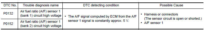
DTC DETECTION LOGIC
To judge the malfunction, the diagnosis checks that the A/F signal computed by ECM from the A/F sensor 1 signal is not inordinately high.
DTC CONFIRMATION PROCEDURE
1.PRECONDITIONING
If DTC Confirmation Procedure has been previously conducted, always preform the following before conducting the next test.
- Turn ignition switch OFF and wait at least 10 seconds.
- Turn ignition switch ON.
- Turn ignition switch OFF and wait at least 10 seconds.
TESTING CONDITION: Before performing the following procedure, confirm that battery voltage is more than 10.5 V at idle.
2.CHECK A/F SENSOR 1 FUNCTION
With CONSULT
- Start engine and warm it up to normal operating temperature.
- Select "A/F SEN1 (B1)" or "A/F SEN1 (B2)" in "DATA MONITOR" mode with CONSULT.
- Check "A/F SEN1 (B1)" or "A/F SEN1 (B2)" indication.
With GST
Follow the procedure "With CONSULT" above
3.PERFORM DTC CONFIRMATION PROCEDURE
With CONSULT
- Turn ignition switch OFF and wait at least 10 seconds.
- Turn ignition switch ON.
- Turn ignition switch OFF, wait at least 10 seconds and then restart engine.
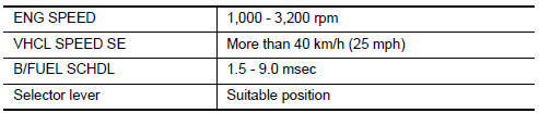
- Drive and accelerate vehicle to more than 40 km/h (25 MPH) within 20 seconds after restarting engine. CAUTION: Always drive vehicle at a safe speed.
- Maintain the following conditions for about 20 consecutive seconds.
NOTE:
- Keep the accelerator pedal as steady as possible during the cruising.
- If this procedure is not completed within 1 minute after restarting engine at step 1, return to step 1.
- Check 1st trip DTC.
With GST
Follow the procedure "With CONSULT" above.
Diagnosis Procedure
1.CHECK GROUND CONNECTION
- Turn ignition switch OFF.
- Check ground connection E9.
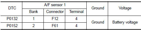
2.CHECK AIR FUEL RATIO (A/F) SENSOR 1 POWER SUPPLY CIRCUIT
- Disconnect A/F sensor 1 harness connector.
- Turn ignition switch ON.
- Check the voltage between A/F sensor 1 harness connector and ground
3.DETECT MALFUNCTIONING PART
Check the following.
- IPDM E/R harness connector F10
- 15 A fuse (No. 37)
- Harness for open or shrt between A/F sensor 1 and fuse
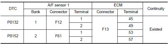
4.CHECK A/F SENSOR 1 INPUT SIGNAL CIRCUIT FOR OPEN AND SHORT
- Turn ignition switch OFF.
- Disconnect ECM harness connector.
- Check the continuity between A/F sensor 1 harness connector and ECM harness connector
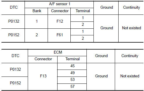
- Check the continuity between A/F sensor 1 harness connector and ground, or ECM harness connector and ground.
- Also check harness for short to power.
5.CHECK INTERMITTENT INCIDENT
6.REPLACE AIR FUEL RATIO (A/F) SENSOR 1
Replace malfunctioning air fuel ratio (A/F) sensor 1.
CAUTION:
- Discard any A/F sensor which has been dropped from a height of more than 0.5 m (19.7 in) onto a hard surface such as a concrete floor; use a new one.
- Before installing new A/F sensor, clean exhaust system threads using Oxygen Sensor Thread Cleaner [commercial service tool (J-43897-18 or J-43897-12)] and approved anti-seize lubricant (commercial service tool).
 P0131, P0151 A/F sensor 1
Description
The air fuel ratio (A/F) sensor 1 is a planar one-cell limit current sensor.
The sensor element of the A/F sensor 1 is composed an electrode
layer, which transports ions. It has ...
 P0137, P0157 HO2S2
Description
The heated oxygen sensor 2, after three way catalyst (manifold),
monitors the oxygen level in the exhaust gas on each bank.
Even if switching characteristics of the air fuel rati ...
Other materials:
P0442 evap control system
DTC Logic
DTC DETECTION LOGIC
This diagnosis detects leakage in the EVAP purge line using engine intake
manifold vacuum.
If pressure does not increase, the ECM will check for leakage in the line
between the fuel tank and EVAP canister
purge volume control solenoid valve, under the followi ...
Vehicle load capacity
Do not exceed the load limit of your vehicle
shown as "The combined weight of
occupants and cargo" on the Tire and
Loading Information label. Do not exceed
the number of occupants shown as
"Seating Capacity" on the Tire and Loading
Information label.
To get "the combined weight of occupants ...
Audio antenna
Location of Antenna
AV control unit
AV control unit antenna feeder
In-line connectors M103, M501
Antenna amp.
Window antenna
Satellite radio antenna feeder
Satellite radio antenna
Window Antenna Repair
ELEMENT CHECK
Attach probe circuit tester (ohm setting) to antenna ...
Nissan Maxima Owners Manual
- Illustrated table of contents
- Safety-Seats, seat belts and supplemental restraint system
- Instruments and controls
- Pre-driving checks and adjustments
- Monitor, climate, audio, phone and voice recognition systems
- Starting and driving
- In case of emergency
- Appearance and care
- Do-it-yourself
- Maintenance and schedules
- Technical and consumer information
Nissan Maxima Service and Repair Manual

0.008