Nissan Maxima Service and Repair Manual: P0131, P0151 A/F sensor 1
Description
The air fuel ratio (A/F) sensor 1 is a planar one-cell limit current sensor.
The sensor element of the A/F sensor 1 is composed an electrode layer, which transports ions. It has a heater in the element.
The sensor is capable of precise measurement = 1, but also in the lean and rich range. Together with its control electronics, the sensor outputs a clear, continuous signal throughout a wide range.
The exhaust gas components diffuse via the diffusion layer at the sensor cell. An electrode layer is applied voltage, and this current relative oxygen density in lean. Also this current relative hydrocarbon density in rich.
Therefore, the A/F sensor 1 is able to indicate air fuel ratio by this electrode layer of current. In addition, a heater is integrated in the sensor to ensure the required operating temperature of about 800C (1,472F).
DTC Logic
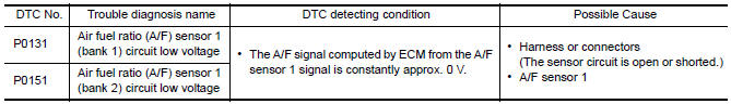
DTC DETECTION LOGIC
To judge the malfunction, the diagnosis checks that the A/F signal computed by ECM from the A/F sensor 1 signal is not inordinately low.
DTC CONFIRMATION PROCEDURE
1.PRECONDITIONING
If DTC Confirmation Procedure has been previously conducted, always perform the following before conducting the next test.
- Turn ignition switch OFF and wait at least 10 seconds.
- Turn ignition switch ON.
- Turn ignition switch OFF and wait at least 10 seconds.
TESTING CONDITION: Before performing the following procedure, confirm that battery voltage is more than 10.5 V at idle.
2.CHECK A/F SENSOR 1 FUNCTION
With CONSULT
- Start engine and warm it up to normal operating temperature.
- Select "A/F SEN1 (B1)" or "A/F SEN1 (B2)" in "DATA MONITOR" mode with CONSULT.
- Check "A/F SEN1 (B1)" or "A/F SEN1 (B2)" indication.
With GST
Follow the procedure "With CONSULT" above.
3.PERFORM DTC CONFIRMATION PROCEDURE
With CONSULT
- Turn ignition switch OFF, wait at least 10 seconds.
- Turn ignition switch ON.
- Turn ignition switch OFF, wait at least 10 seconds and then restart engine.
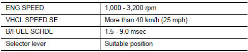
- Drive and accelerate vehicle to more than 40 km/h (25 MPH) within 20 seconds after restarting engine. CAUTION: Always drive vehicle at a safe speed.
- Maintain the following conditions for about 20 consecutive seconds.
NOTE:
- Keep the accelerator pedal as steady as possible during cruising.
- If this procedure is not completed within 1 minute after restarting engine at step 1, return to step 1.
- Check 1st trip DTC.
With GST
Follow the procedure "With CONSULT" above.
Diagnosis Procedure
1.CHECK GROUND CONNECTION
- Turn ignition switch OFF.
- Check ground connection E9.
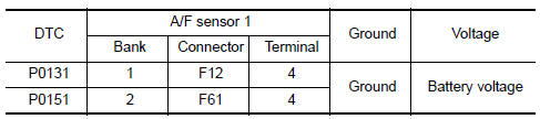
2.CHECK AIR FUEL RATIO (A/F) SENSOR 1 POWER SUPPLY CIRCUIT
- Disconnect A/F sensor 1 harness connector.
- Turn ignition switch ON.
- Check the voltage between A/F sensor 1 harness connector and ground.
3.DETECT MALFUNCTIONING PART
Check the following.
- IPDM E/R harness connector F10
- 15 A fuse (No. 37)
- Harness for open or short between A/F sensor 1 and fuse
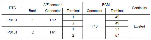
4.CHECK A/F SENSOR 1 INPUT SIGNAL CIRCUIT FOR OPEN AND SHORT
- Turn ignition switch OFF.
- Disconnect ECM harness connector.
- Check the continuity between A/F sensor 1 harness connector and ECM harness connector.
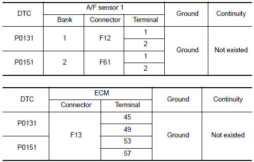
- Check the continuity between A/F sensor 1 harness connector and ground, or ECM harness connector and ground.
- Also check harness for short to power.
5.CHECK INTERMITTENT INCIDENT
6.REPLACE AIR FUEL RATIO (A/F) SENSOR 1
Replace malfunctioning air fuel ratio (A/F) sensor 1.
CAUTION:
- Discard any A/F sensor which has been dropped from a height of more than 0.5 m (19.7 in) onto a hard surface such as a concrete floor; use a new one.
- Before installing new A/F sensor, clean exhaust system threads using Oxygen Sensor Thread Cleaner [commercial service tool (J-43897-18 or J-43897-12)] and approved anti-seize lubricant (commercial service tool).
 P0130, P0150 A/F sensor 1
Description
The air fuel ratio (A/F) sensor 1 is a planar one-cell limit current sensor.
The sensor element of the A/F sensor 1 is composed an electrode
layer, which transports ions. It has ...
 P0132, P0152 A/F sensor 1
Description
The air fuel ratio (A/F) sensor 1 is a planar one-cell limit current sensor.
The sensor element of the A/F sensor 1 is composed an electrode
layer, which transports ions. It has ...
Other materials:
Oil Pan And Oil Strainer
Exploded View
Oil pan baffle
O-ring
Gasket
Oil pressure switch
Oil cooler gasket
Oil cooler
Oil cooler connection
Oil filter
Lower oil pan
Oil strainer
Rear plate cover
Crankshaft position sensor (POS)
O-ring
Upper oil pan
Removal and Installation (Lower O ...
Headlamp
System Diagram
System Description
Control of the headlamp system operation is dependent upon the position of
the combination switch (lighting and turn signal switch). When the lighting
switch is placed in the 2nd position, the BCM (body control module) receives
input requesting the headlam ...
Front sunroof glass
Removal and Installation
REMOVAL
Remove the wind deflector. Refer to RF-168, "Removal and
Installation".
Tape down the glass lid weatherstrip along the from sunroof glass
with protective tape.
Apply protective tape around the front sunroof glass to protect
the surface from damage.
...
Nissan Maxima Owners Manual
- Illustrated table of contents
- Safety-Seats, seat belts and supplemental restraint system
- Instruments and controls
- Pre-driving checks and adjustments
- Monitor, climate, audio, phone and voice recognition systems
- Starting and driving
- In case of emergency
- Appearance and care
- Do-it-yourself
- Maintenance and schedules
- Technical and consumer information
Nissan Maxima Service and Repair Manual

0.0056