Nissan Maxima Service and Repair Manual: On board diagnostic (OBD) system
Diagnosis Description
DESCRIPTION
The CVT system has two self-diagnostic systems.
The first is the emission-related on board diagnostic system (OBD-II) performed by the TCM in combination with the ECM. A malfunction is indicated by the MIL (Malfunction Indicator Lamp) and is stored as a DTC in the ECM memory and in the TCM memory.
The second is the TCM original self-diagnosis performed by the TCM. A malfunction history is stored in the TCM memory. The detected items are overlapped with OBD-II self-diagnostic items. For details, refer to TM- 124, "DTC Index".
OBD-II FUNCTION
The ECM provides emission-related on board diagnostic (OBD-II) functions for the CVT system. One function is to receive a signal from the TCM used with OBD-related parts of the CVT system. The signal is sent to the ECM when a malfunction occurs in the corresponding OBD-related part. The other function is to indicate a diagnostic result by means of the MIL (Malfunction Indicator Lamp) on the instrument panel. Sensors, switches and solenoid valves are used as sensing elements.
The MIL automatically illuminates in "One or Two Trip Detection Logic" when a malfunction is sensed in relation to CVT system parts.
ONE OR TWO TRIP DETECTION LOGIC OF OBD-II
One Trip Detection Logic If a malfunction is sensed during the first test drive, the MIL illuminates and the ECM memory stores the malfunction as a DTC. The TCM is not provided with such a memory function.
Two Trip Detection Logic
When a malfunction is sensed during the first test drive, it is stored in the ECM memory as a 1st trip DTC (diagnostic trouble code) or 1st trip freeze frame data. At this point, the MIL does not illuminate. - 1st trip If the same malfunction as that experienced during the first test drive is sensed during the second test drive, the MIL will illuminate. - 2nd trip The "trip" in the "One or Two Trip Detection Logic" means a driving mode in which self-diagnosis is performed during vehicle operation.
OBD-II DIAGNOSTIC TROUBLE CODE (DTC)
How to Read DTC and 1st Trip DTC
DTC and 1st trip DTC can be read by the following methods.
( with CONSULT or
 GST) CONSULT or GST (Generic Scan
Tool) Examples: P0705, P0720, etc.
GST) CONSULT or GST (Generic Scan
Tool) Examples: P0705, P0720, etc.
These DTC are prescribed by SAE J2012.
(CONSULT also displays the malfunctioning component or system.)
- 1st trip DTC No. is the same as DTC No.
- Output of the diagnostic trouble code indicates that the indicated circuit has a malfunction. However, in case of the Mode II and GST, they do not indicate whether the malfunction is still occurring or it occurred in the past and has returned to normal. CONSULT can identify them as shown below, therefore, CONSULT (if available) is recommended.
- DTC or 1st trip DTC of a malfunction is displayed in SELF-DIAGNOSTIC RESULTS mode for "ENGINE" with CONSULT. Time data indicates how many times the vehicle was driven after the last detection of a DTC.
- If the DTC is being detected currently, the time data will be "0".
- If a 1st trip DTC is stored in the ECM, the time data will be "1t".
Freeze Frame Data and 1st Trip Freeze Frame Data
- The ECM has a memory function, which stores the driving conditions
such as fuel system status, calculated
load value, engine coolant temperature, short-term fuel trim, long-term fuel
trim, engine speed and vehicle
speed at the moment the ECM detects a malfunction.
Data that are stored in the ECM memory, along with the 1st trip DTC, are called 1st trip freeze frame data, and the data, stored together with the DTC data, are called freeze frame data and displayed on CONSULT or GST. The 1st trip freeze frame data can only be displayed on the CONSULT screen, not on the GST.
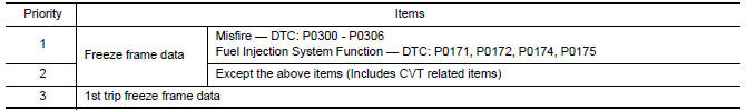
Only one set of freeze frame data (either 1st trip freeze frame data or freeze frame data) can be stored in the ECM. 1st trip freeze frame data is stored in the ECM memory along with the 1st trip DTC. There is no priority for 1st trip freeze frame data, and it is updated each time a different 1st trip DTC is detected. However, once freeze frame data (2nd trip detection/MIL on) is stored in the ECM memory, 1st trip freeze frame data is no longer stored. Remember, only one set of freeze frame data can be stored in the ECM. The ECM has the following priorities to update the data.
Both 1st trip freeze frame data and freeze frame data (along with the DTC) are cleared when the ECM memory is erased.
How to Erase DTC
- The diagnostic trouble code can be erased by CONSULT, GST or ECM
DIAGNOSTIC TEST MODE as
described below.
- If the battery cable is disconnected, the diagnostic trouble code will be lost within 24 hours.
- When erasing the DTC, using CONSULT or GST is easier and quicker than switching the mode selector on the ECM.
- The following emission-related diagnostic information is cleared
from the ECM memory when erasing DTC
related to OBD-II. For details, refer to EC-542, "DTC Index".
- Diagnostic trouble codes (DTC)
- 1st trip diagnostic trouble codes (1st trip DTC)
- Freeze frame data
- 1st trip freeze frame data
- System readiness test (SRT) codes
- Test values
 How to Erase DTC (With CONSULT)
The emission related diagnostic information in the TCM and ECM can be erased by selecting "ALL Erase" in the "Description" of "FINAL CHECK" mode with CONSULT.
 How to Erase DTC (With GST)
- If the ignition switch stays ON after repair work, be sure to turn ignition switch OFF once. Wait at least 10 seconds and then turn it ON (engine stopped) again.
- Select Mode 4 with GST (Generic Scan Tool).
MALFUNCTION INDICATOR LAMP (MIL)
Description
The MIL is located on the instrument panel.
- The MIL is turned ON when the ignition switch is turned ON
without the engine running. This is a bulb check.
- If the MIL is not turned ON, refer to EC-507, "Component Function Check".
- Turn OFF the MIL when the engine is started.
If the MIL remains ON, the on board diagnostic system has detected an engine system malfunction.
 Shift lock system
System Diagram
System Description
The selector lever cannot be shifted from "P" position to any other position
unless the ignition switch is in the
ON position and the brake pedal is depressed ...
 Diagnosis system (TCM)
CONSULT Function
FUNCTION
CONSULT can display each diagnostic item using the diagnostic test modes
shown following.
WORK SUPPORT MODE
Display Item List
Engine Brake Adjustment
CAUTION:
Mo ...
Other materials:
Diagnosis system (AV control unit)
Diagnosis Description
MULTIFUNCTION SWITCH AND PRESET SWITCH SELF-DIAGNOSIS FUNCTION
The ON/OFF operation (continuity) of each switch in the multifunction switch
and preset switch can be checked.
Self-Diagnosis Mode
Press the BACK switch and the
switch of the 8-direction switches with ...
Power steering oil pump
Exploded View
Rear bracket
Power steering oil pump assembly
Front bracket
Removal and Installation
NOTE: When removing components such as
hoses, tubes/lines, etc., cap or plug openings to prevent fluid from spilling.
REMOVAL
Remove front wheel and tire (RH) using power tool. ...
Telescopic sensor
Description
The telescopic sensor is installed to the steering column assembly.
The pulse signal is input to the driver seat control unit when
telescopic is performed.
The driver seat control unit counts the pulse and calculates the
telescopic amount of the steering column.
Componen ...
Nissan Maxima Owners Manual
- Illustrated table of contents
- Safety-Seats, seat belts and supplemental restraint system
- Instruments and controls
- Pre-driving checks and adjustments
- Monitor, climate, audio, phone and voice recognition systems
- Starting and driving
- In case of emergency
- Appearance and care
- Do-it-yourself
- Maintenance and schedules
- Technical and consumer information
Nissan Maxima Service and Repair Manual

0.0056