Nissan Maxima Owners Manual: Vehicle load capacity
Do not exceed the load limit of your vehicle shown as "The combined weight of occupants and cargo" on the Tire and Loading Information label. Do not exceed the number of occupants shown as "Seating Capacity" on the Tire and Loading Information label.
To get "the combined weight of occupants and cargo", add the weight of all occupants, then add the total luggage weight. Examples are shown in the following illustration.
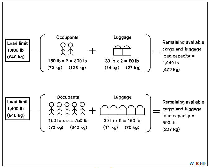 >
Example
>
Example
Steps for determining correct load limit
1. Locate the statement "The combined weight of occupants and cargo should never exceed XXX lbs or XXX kg" on your vehicle's placard.
2. Determine the combined weight of the driver and passengers that will be riding in your vehicle.
3. Subtract the combined weight of the driver and passengers from XXX lbs or XXX kg.
4. The resulting figure equals the available amount of cargo and luggage load capacity. For example, if the XXX amount equals 1,400 lbs. and there will be five 150 lb. passengers in your vehicle, the amount of available cargo and luggage load capacity is 650 lbs. (1,400-750 (5 X 150) = 650 lbs) or (640-340 (5 X 70) = 300 kg.) 5. Determine the combined weight of luggage and cargo being loaded on the vehicle. That weight may not safely exceed the available cargo and luggage load capacity calculated in step 4.
Before driving a loaded vehicle, confirm that you do not exceed the Gross Vehicle Weight Rating (GVWR) or the Gross Axle Weight Rating (GAWR) for your vehicle.
For additional information, refer to "Measurement of weights" in this section.
Also check tires for proper inflation pressures.
For additional information, refer to "Tire and loading information label" in this section.
 Terms
Terms
It is important to familiarize yourself with
the following terms before loading your
vehicle:
Curb Weight (actual weight of your
vehicle) - vehicle weight including:
standard and optional eq ...
 Loading tips
The GVW must not exceed GVWR
or GAWR as specified on the
F.M.V.S.S./C.M.V.S.S. certification
label.
Do not load the front and rear axle to
the GAWR. Doing so will exceed the
GVWR.
WA ...
Other materials:
FEB system limitations
WARNING
Listed below are the system limitations for
the FEB system. Failure to operate the
vehicle in accordance with these system
limitations could result in serious injury or
death.
The FEB system cannot detect all vehicles
under all conditions.
The radar sensor does not detect the
follow ...
Precaution
PRECAUTIONS
Precautions for Trouble Diagnosis
CAUTION:
Never apply 7.0 V or more to the measurement terminal.
Use a tester with open terminal voltage of 7.0 V or less.
Turn the ignition switch OFF and disconnect the battery cable from the
negative terminal when checking the harness.
P ...
Engine compartment check locations
VQ35DE engine
1. Engine coolant reservoir
2. Drive belt location
3. Engine oil filler cap
4. Brake fluid reservoir
5. Air cleaner
6. Fuse block
7. Fuse block/Fusible links
8. Fusible links
9. Battery
10. Engine oil dipstick
11. Radiator cap
12. Power steering fluid reservoir
13. Win ...
Nissan Maxima Owners Manual
- Illustrated table of contents
- Safety-Seats, seat belts and supplemental restraint system
- Instruments and controls
- Pre-driving checks and adjustments
- Monitor, climate, audio, phone and voice recognition systems
- Starting and driving
- In case of emergency
- Appearance and care
- Do-it-yourself
- Maintenance and schedules
- Technical and consumer information
Nissan Maxima Service and Repair Manual

0.0053