Nissan Maxima Service and Repair Manual: Audio antenna
Location of Antenna
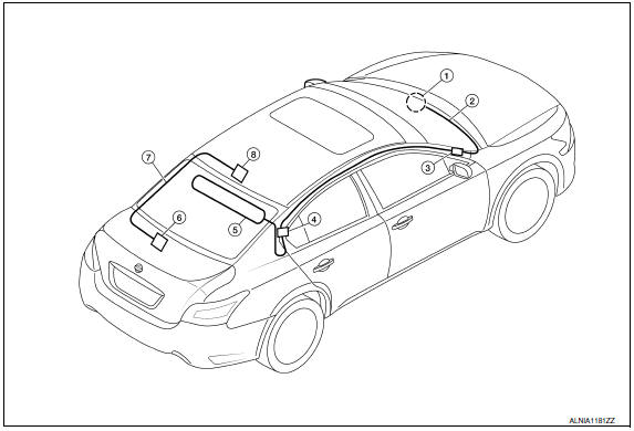
- Audio unit
- Audio unit antenna feeder
- In-line connectors M103, M501
- Antenna amp.
- Window antenna
- Satellite radio tuner
- Satellite radio antenna feeder
- Satellite radio antenna
Window Antenna Repair
ELEMENT CHECK
- Attach probe circuit tester (ohm setting) to antenna terminal on each side.
- When measuring continuity, wrap tin foil around the top of probe. Then, press the foil against the wire with your finger.
- If an element is broken, no continuity will exist.
- To locate a break, move probe along element. Tester indication will change abruptly when probe passes the broken point.
REPAIR EQUIPMENT
- Conductive silver composition (DuPont No. 4817 or equivalent)
- Ruler 30 cm (11.8 in) long
- Drawing pen
- Heat gun
- Alcohol
- Cloth
REPAIRING PROCEDURE
- Wipe broken heat wire and its surrounding area clean with a cloth dampened in alcohol.
- Apply a small amount of conductive silver composition to tip of drawing pen. NOTE: Shake silver composition container before use.
- Place ruler on glass along broken line. Deposit conductive silver composition on break with drawing pen. Slightly overlap existing heat wire on both sides [preferably 5 mm (0.20 in)] of the break.
- After repair has been completed, check repaired wire for continuity.
This check should be conducted 10 minutes after silver composition is deposited.
Do not touch repaired area while test is being conducted.
- Apply a constant stream of hot air directly to the repaired area for
approximately 20 minutes with a heat gun. A minimum distance of 3 cm (1.2
in) should be kept between repaired area and hot air outlet.
If a heat gun is not available, let the repaired area dry for 24 hours.
 Steering switch
Removal and Installation
REMOVAL
Remove the driver airbag module. Refer to SR-12, "Removal and
Installation".
Remove the steering wheel audio control switch screws (A).
Release the steer ...
 Antenna AMP
Removal and Installation
REMOVAL
Remove the rear pillar finisher RH. Refer to INT-27, "Exploded
View".
Detach the antenna amp. harness clip (A).
Disconnect the harness connectors ( ...
Other materials:
Audio antenna
Location of Antenna
AV control unit
AV control unit antenna feeder
In-line connectors M103, M501
Antenna amp.
Window antenna
Satellite radio antenna feeder
Satellite radio antenna
Window Antenna Repair
ELEMENT CHECK
Attach probe circuit tester (ohm setting) to antenna ...
Back-up lamp
Wiring Diagram
...
Rear Cross Traffic Alert (RCTA) (if so equipped)
WARNING
Failure to follow the warnings and instructions
for proper use of the RCTA system
could result in serious injury or death.
The RCTA system is not a replacement
for proper driving procedures and is not
designed to prevent contact with vehicles
or objects. When backing out of a
...
Nissan Maxima Owners Manual
- Illustrated table of contents
- Safety-Seats, seat belts and supplemental restraint system
- Instruments and controls
- Pre-driving checks and adjustments
- Monitor, climate, audio, phone and voice recognition systems
- Starting and driving
- In case of emergency
- Appearance and care
- Do-it-yourself
- Maintenance and schedules
- Technical and consumer information
Nissan Maxima Service and Repair Manual

0.0079