Nissan Maxima Service and Repair Manual: B2581, B2582 intake sensor
Description
Intake Sensor
- The intake sensor is located on the evaporator.
- It converts air temperature after it passes through the evaporator into a resistance value which is then input to the A/C auto amp.
Intake Sensor Circuit
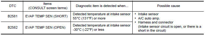
DTC Logic
DTC DETECTION LOGIC
NOTE: If DTC is displayed along with DTC U1000 or U1010, first diagnose the DTC U1000 or U1010.
DTC CONFIRMATION PROCEDURE
1.CHECK WITH SELF-DIAGNOSIS FUNCTION OF CONSULT
- Using CONSULT, perform "SELF-DIAGNOSIS RESULTS" of HVAC.
- Check if any DTC No. is displayed in the self-diagnosis results.
NOTE: If DTC is displayed along with DTC U1000 or U1010, first diagnose the DTC U1000 or U1010.
Diagnosis Procedure
1.CHECK INTAKE SENSOR POWER SUPPLY
- Disconnect intake sensor connector.
- Turn ignition switch ON.
- Check voltage between intake sensor harness connector M69 terminal 1 and ground.
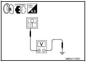
1 - Ground: Approx. 5V
2.CHECK CONTINUITY BETWEEN INTAKE SENSOR AND A/C AUTO AMP.
- Turn ignition switch OFF.
- Disconnect A/C auto amp. connector.
- Check continuity between intake sensor harness connector M69 (A) terminal 2 and A/C auto amp. harness connector M37 (B) terminal 37.
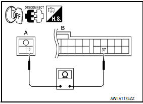
2 - 37: Continuity should exist.
3.CHECK INTAKE SENSOR
Check intake sensor.
4.CHECK CONTINUITY BETWEEN INTAKE SENSOR AND A/C AUTO AMP.
- Turn ignition switch OFF.
- Disconnect A/C auto amp. connector.
- Check continuity between intake sensor harness connector M69 (A) terminal 1 and A/C auto amp. harness connector M37 (B) terminal 16.
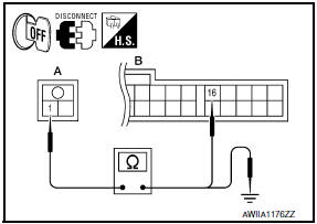
1 - 16: Continuity should exist.
- Check continuity between intake sensor harness connector M69 (A) terminal 1 and ground.
1 - Ground: Continuity should not exist.
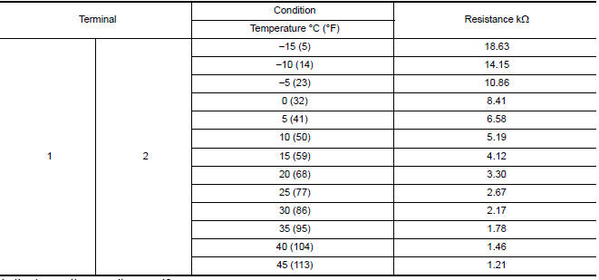
Component Inspection
1.CHECK INTAKE SENSOR
- Turn ignition switch OFF.
- Disconnect intake sensor connector.
- Check resistance between intake sensor terminals.
 B2578, B2579 in-vehicle sensor
Description
In-vehicle Sensor
The in-vehicle sensor (1) is located on instrument lower cover
(LH).
It converts variations in compartment air temperature drawn from
the aspirator into a ...
 B2630, B2631 sunload sensor
Description
COMPONENT DESCRIPTION
Sunload Sensor
The sunload sensor (1) is located on the driver side defroster
grille.
It detects sunload entering through windshield by means of a
photo ...
Other materials:
Programming HomeLink for Canadian customers and gate openers
Canadian radio-frequency laws require transmitter
signals to "time-out" (or quit) after several
seconds of transmission - which may not be long
enough for HomeLink to pick up the signal
during training. Similar to this Canadian law,
some U.S. gate operators are designed to "timeout"
in the sam ...
Intermittent incident
Inspection Procedure
INTERMITTENT TROUBLE
An intermittent incident may have occured in the past but is not being
detected currently. This DTC will not bedetected on SELF DIAG [CURRENT], but
may be viewed on SELF DIAG [PAST] using CONSULT.
Trouble Diagnosis with CONSULT
DIAGNOSTIC PROCEDURE 4 ...
Power control system
System Diagram
System Description
COOLING FAN CONTROL
IPDM E/R controls cooling fans according to the status of the cooling fan
speed request signal received from
ECM via CAN communication.
GENERATOR CONTROL
IPDM E/R outputs power generation command signal (PWM signal) to the
generat ...
Nissan Maxima Owners Manual
- Illustrated table of contents
- Safety-Seats, seat belts and supplemental restraint system
- Instruments and controls
- Pre-driving checks and adjustments
- Monitor, climate, audio, phone and voice recognition systems
- Starting and driving
- In case of emergency
- Appearance and care
- Do-it-yourself
- Maintenance and schedules
- Technical and consumer information
Nissan Maxima Service and Repair Manual

0.0075