Nissan Maxima Service and Repair Manual: B2630, B2631 sunload sensor
Description
COMPONENT DESCRIPTION
Sunload Sensor
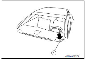
- The sunload sensor (1) is located on the driver side defroster grille.
- It detects sunload entering through windshield by means of a photo diode. The sensor converts the sunload into a current value, which is then input into the A/C auto amp.
Sunload Sensor Circuit
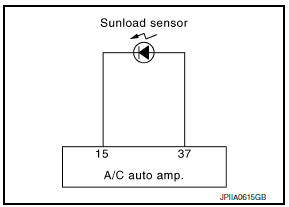
SUNLOAD INPUT PROCESS
The A/C auto amp. also equips a processing circuit which averages the variations in detected sunload over a period of time. This prevents drastic swings in the air temperature control system operation due to small or quick variations in detected sunload.
For example, consider driving along a road bordered by an occasional group of large trees. The sunload detected by the sunload sensor varies whenever the trees obstruct the sunlight. The processing circuit averages the detected sunload over a period of time, so that the (insignificant) effect of the trees momentarily obstructing the sunlight does not cause any change in the air temperature control system operation. On the other hand, shortly after entering a long tunnel, the system recognizes the change in sunload, and the system reacts accordingly.
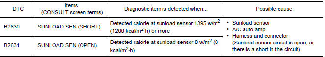
DTC Logic
DTC DETECTION LOGIC
NOTE:
- If DTC is displayed along with DTC U1000 or U1010, first diagnose the DTC U1000 or U1010. Refer to HAC- 133, "DTC Logic" or HAC-134, "DTC Logic".
- Sunload sensor may register a malfunction when indoors, at
dusk, or at other times when light is insufficient.
When performing the diagnosis indoors, light the sunload sensor with a lamp (60W or more).
DTC CONFIRMATION PROCEDURE
1.CHECK WITH SELF-DIAGNOSIS FUNCTION OF CONSULT
- Using CONSULT, perform "SELF-DIAGNOSIS RESULTS" of HVAC.
- Check if any DTC No. is displayed in the self-diagnosis results.
NOTE:
- If DTC is displayed along with DTC U1000 or U1010, first diagnose the DTC U1000 or U1010. Refer to HAC- 133, "DTC Logic" or HAC-134, "DTC Logic".
- Sunload sensor may register a malfunction when indoors, at
dusk, or at other times when light is insufficient.
When performing the diagnosis indoors, light the sunload sensor with a lamp (60W or more).
Diagnosis Procedure
1.CHECK SUNLOAD SENSOR POWER SUPPLY
- Disconnect sunload sensor connector.
- Turn ignition switch ON.
- Check voltage between sunload sensor harness connector M56 terminal 1 and ground.
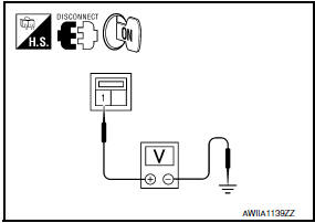
1 - Ground: Approx. 5V
2.CHECK CONTINUITY BETWEEN SUNLOAD SENSOR AND A/C AUTO AMP.
- Turn ignition switch OFF.
- Disconnect A/C auto amp. connector.
- Check continuity between sunload sensor harness connector M56 (A) terminal 2 and A/C auto amp. harness connector M37 (B) terminal 37.
2 - 37: Continuity should exist.
3.CHECK SUNLOAD SENSOR
- Reconnect sunload sensor connector and A/C auto amp. connector.
- Check sunload sensor.
4.CHECK CONTINUITY BETWEEN SUNLOAD SENSOR AND A/C AUTO AMP.
- Turn ignition switch OFF.
- Disconnect A/C auto amp. connector.
- Check continuity between sunload sensor harness connector M56 (A) terminal 1 and A/C auto amp. harness connector M37 (B) terminal 15.
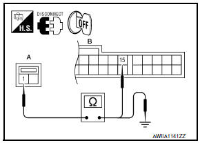
1 - 15: Continuity should exist.
- Check continuity between sunload sensor harness connector M56 (A) terminal 1 and ground.
1 - Ground: Continuity should not exist.
Component Inspection
1.CHECK SUNLOAD SENSOR
- Turn ignition switch ON.
- Check voltage between A/C auto amp. harness connector and ground.
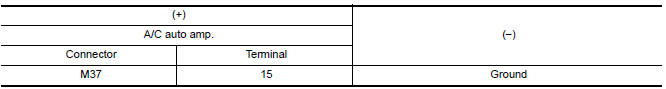
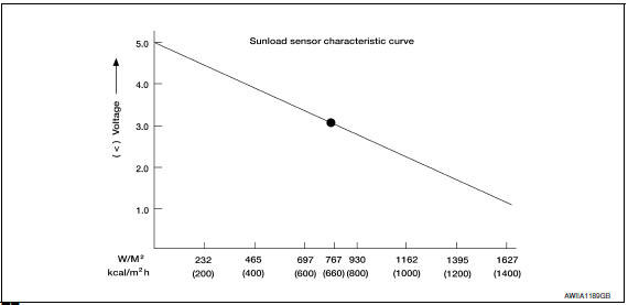
NOTE: Select a place in direct sunlight when checking sunload sensor.
 B2581, B2582 intake sensor
Description
Intake Sensor
The intake sensor is located on the evaporator.
It converts air temperature after it passes through the evaporator
into a resistance value which is then input to the ...
 B2632, B2633 air mix door motor (driver side)
Description
COMPONENT DESCRIPTION
Air Mix Door Motor (driver side)
The air mix door motor (driver side) (1) is attached to the heater
&
cooling unit assembly.
It rotates so that the a ...
Other materials:
Configuration (BCM)
CONFIGURATION (BCM) : Description
Vehicle specification needs to be written with CONSULT because it is not
written after replacing BCM.
Configuration has three functions as follows
Function
Description
"Before Replace ECU "
Reads the vehi ...
Symptom diagnosis
SQUEAK AND RATTLE TROUBLE DIAGNOSES
Work Flow
CUSTOMER INTERVIEW
Interview the customer if possible, to determine the conditions that exist
when the noise occurs. Use the Diagnostic Worksheet during the interview to
document the facts and conditions when the noise occurs and any customer' ...
Changing engine oil
1. Park the vehicle on a level surface and apply
the parking brake.
2. Start the engine and let it idle until it reaches
operating temperature, then turn it off.
3. Remove the oil filler cap A by turning it
counterclockwise.
4. Remove clips B from the under-engine protector.
5 ...
Nissan Maxima Owners Manual
- Illustrated table of contents
- Safety-Seats, seat belts and supplemental restraint system
- Instruments and controls
- Pre-driving checks and adjustments
- Monitor, climate, audio, phone and voice recognition systems
- Starting and driving
- In case of emergency
- Appearance and care
- Do-it-yourself
- Maintenance and schedules
- Technical and consumer information
Nissan Maxima Service and Repair Manual

0.0064