
Nissan Maxima Owners Manual: Changing engine oil
1. Park the vehicle on a level surface and apply the parking brake.
2. Start the engine and let it idle until it reaches operating temperature, then turn it off.
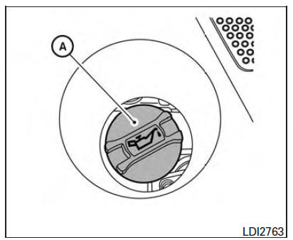
3. Remove the oil filler cap A by turning it counterclockwise.
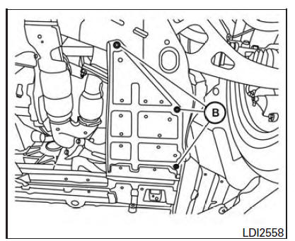
4. Remove clips B from the under-engine protector.
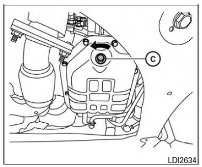
5. Place a large drain pan under the drain plug C .
6. Remove the drain plug C with a wrench by turning it counterclockwise and completely drain the oil.
If the engine oil filter is to be changed, remove and replace it at this time. For additional information, refer to "Changing engine oil filter" in this section.
- Waste oil must be disposed of properly.
- Check your local regulations.
WARNING
- Prolonged and repeated contact with used engine oil may cause skin cancer.
- Try to avoid direct skin contact with used oil. If skin contact is made, wash thoroughly with soap or hand cleaner as soon as possible.
- Keep used engine oil out of reach of children.
CAUTION
Be careful not to burn yourself. The engine oil may be hot.
7. Clean and reinstall the drain plug and a new washer. Securely tighten the drain plug with a wrench. Do not use excessive force.
Drain plug tightening torque: 25 ft-lb (34 N*m)
8. Refill engine with recommended oil through the oil filler opening, then install the oil filler cap securely.
For additional information on drain and refill capacity, refer to "Recommended fluids/lubricants and capacities" in the "Technical and consumer information" section of this manual.
The drain and refill capacity depends on the oil temperature and drain time. Use these specifications for reference only. Always use the dipstick to determine when the proper amount of oil is in the engine.
9. Start the engine. Check for leakage around the drain plug and oil filter. Correct as required.
10. Turn the engine off and wait more than 10 minutes. Check the oil level with the dipstick. Add engine oil if necessary.
 Checking engine oil level
1. Park the vehicle on a level surface and apply
the parking brake.
2. Start the engine and let it idle until it reaches
operating temperature.
3. Turn off the engine. Wait more than
10 m ...
 Changing engine oil filter
1. Park the vehicle on a level surface and apply
the parking brake.
2. Turn the engine off.
3. Place a large drain pan under the oil filter B .
4. Remove clips A from the right engine prot ...
Other materials:
Blocking wheels
A. Blocks
B. Flat tire
Place suitable blocks at both the front and back
of the wheel diagonally opposite the flat tire to
prevent the vehicle from moving when it is jacked
up.
WARNING
Be sure to block the wheel as the vehicle
may move and result in personal injury.
Getting the spare tir ...
Removal and installation
WHEEL HUB
Removal and Installation
Knuckle
Baffle plate
Wheel hub assembly
Brake rotor
Wheel nut
Anchor block
Wheel sensor
Parking brake cable
Refer to PB-6, "Exploded View".
Refer to BRC-103, "Removal and Installation
- Rear Wheel Sensor".
&nb ...
Unit disassembly and assembly
DOOR MIRROR
Exploded View
Door mirror glass
Actuator assembly
Door mirror assembly
Disassembly
Turn the door mirror glass surface upward.
Pull from the bottom to disengage lower clips
Lift to disengage the upper mirror hooks (A).
Disconnect the harness connect ...
Nissan Maxima Owners Manual
- Illustrated table of contents
- Safety-Seats, seat belts and supplemental restraint system
- Instruments and controls
- Pre-driving checks and adjustments
- Monitor, climate, audio, phone and voice recognition systems
- Starting and driving
- In case of emergency
- Appearance and care
- Do-it-yourself
- Maintenance and schedules
- Technical and consumer information
Nissan Maxima Service and Repair Manual

0.0364