Nissan Maxima Service and Repair Manual: P0453 evap control system pressure sensor
Description
The EVAP control system pressure sensor detects pressure in the purge line. The sensor output voltage to the ECM increases as pressure increases.
DTC Logic
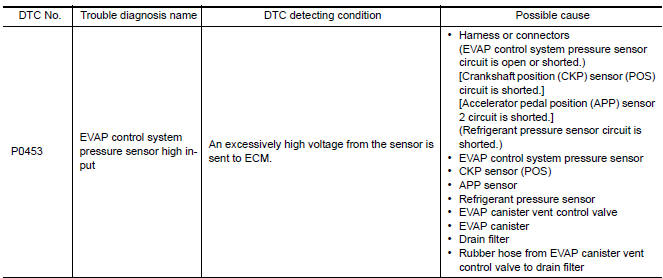
DTC DETECTION LOGIC
DTC CONFIRMATION PROCEDURE
1.PRECONDITIONING
If DTC Confirmation Procedure has been previously conducted, always perform the following before conducting the next test.
- Turn ignition switch OFF and wait at least 10 seconds.
- Turn ignition switch ON.
- Turn ignition switch OFF and wait at least 10 seconds.
TESTING CONDITION: Always perform test at a temperature of 5C (41F) or more.
2.PERFORM DTC CONFIRMATION PROCEDURE
With CONSULT
- Start engine and warm it up to normal operating temperature.
- Turn ignition switch OFF and wait at least 10 seconds.
- Turn ignition switch ON.
- Turn ignition switch OFF and wait at least 10 seconds.
- Turn ignition switch ON.
- Select "DATA MONITOR" mode with CONSULT.
- Check that "FUEL T/TMP SE" is more than 0C (32F).
- Start engine and wait at least 20 seconds.
- Check 1st trip DTC.
With GST
- Start engine and warm it up to normal operating temperature.
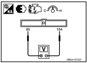
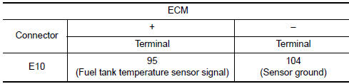
- Set voltmeter probes to ECM harness connector terminals.
- Check that the voltage is less than 4.2 V.
- Turn ignition switch OFF and wait at least 10 seconds.
- Turn ignition switch ON.
- Turn ignition switch OFF and wait at least 10 seconds.
- Start engine and wait at least 20 seconds.
- Check 1st trip DTC.
Diagnosis Procedure
1.CHECK GROUND CONNECTION
- Turn ignition switch OFF.
- Check ground connection E9.
2.CHECK CONNECTOR
- Disconnect EVAP control system pressure sensor harness connector.
- Check that water is not inside connectors.
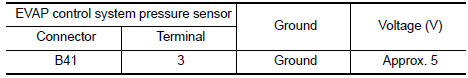
3.CHECK EVAP CONTROL SYSTEM PRESSURE SENSOR POWER SUPPLY CIRCUIT
- Turn ignition switch ON.
- Check the voltage between EVAP control system pressure sensor harness connector and ground.
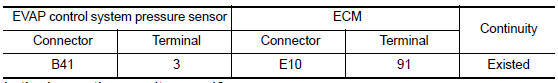
4.CHECK EVAP CONTROL SYSTEM PRESSURE SENSOR POWER SUPPLY CIRCUIT-II
- Turn ignition switch OFF.
- Disconnect ECM harness connector.
- Check the continuity between EVAP control system pressure sensor harness connector and ECM harness connector.
5.DETECT MALFUNCTIONING PART
Check the following.
- Harness connectors B10, E29
- Harness for open or short between EVAP control system pressure sensor and ECM
6.CHECK SENSOR POWER SUPPLY CIRCUIT
Check harness for short to power and short to ground, between the following terminals.
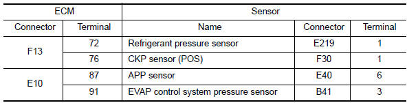
7.CHECK COMPONENTS
Check the following.
- Crankshaft position sensor (POS) (Refer to EC-299, "Component Inspection".)
- Refrigerant pressure sensor
8.CHECK APP SENSOR
9.REPLACE ACCELERATOR PEDAL ASSEMBLY
- Replace accelerator pedal assembly
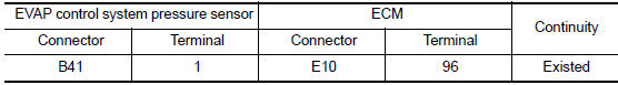
10.CHECK EVAP CONTROL SYSTEM PRESSURE SENSOR GROUND CIRCUIT FOR OPEN AND SHORT
- Turn ignition switch OFF
- Disconnect ECM harness connector.
- Check the continuity between EVAP control system pressure sensor harness connector and ECM harness connector.
- Also check harness for short to ground and short to power.
11.DETECT MALFUNCTIONING PART
Check the following.
- Harness connectors B10, E29
- Harness for open or short between EVAP control system pressure sensor and ECM
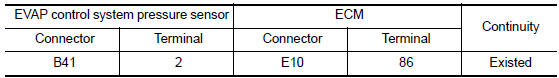
12.CHECK EVAP CONTROL SYSTEM PRESSURE SENSOR INPUT SIGNAL CIRCUIT FOR OPEN AND SHORT
- Check the continuity between EVAP control system pressure sensor harness connector and ECM harness connector.
- Also check harness for short to ground and short to power.
13.DETECT MALFUNCTIONING PART
Check the following.
- Harness connectors B10, E29
- Harness for open or short between EVAP control system pressure sensor and ECM
14.CHECK RUBBER TUBE
- Disconnect rubber tube connected to EVAP canister vent control valve.
- Check the rubber tube for clogging.
15.CHECK EVAP CANISTER VENT CONTROL VALVE
16.CHECK EVAP CONTROL SYSTEM PRESSURE SENSOR
17.CHECK DRAIN FILTER
18.CHECK IF EVAP CANISTER IS SATURATED WITH WATER
- Remove EVAP canister with EVAP canister vent control valve and EVAP control system pressure sensor attached. Refer to FL-14, "Removal and Installation (EVAP Canister)".
- Check if water will drain from the EVAP canister
19.CHECK EVAP CANISTER
Weigh the EVAP canister with the EVAP canister vent control valve and EVAP control system pressure sensor attached.
The weight should be less than 2.1 kg (4.6 lb).
20.DETECT MALFUNCTIONING PART
Check the following.
- EVAP canister for damage
- EVAP hose between EVAP canister and drain filter for clogging or poor connection
21.CHECK INTERMITTENT INCIDENT
Component Inspection
EVAP CONTROL SYSTEM PRESSURE SENSOR
1.CHECK EVAP CONTROL SYSTEM PRESSURE SENSOR
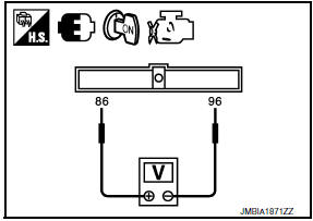
- Turn ignition switch OFF.
- Remove EVAP control system pressure sensor with its harness
connector. Refer to FL-17, "Removal and
Installation".
Always replace O-ring with a new one.
- Install a vacuum pump to EVAP control system pressure sensor.
- Turn ignition switch ON and check output voltage between ECM terminals under the following conditions.
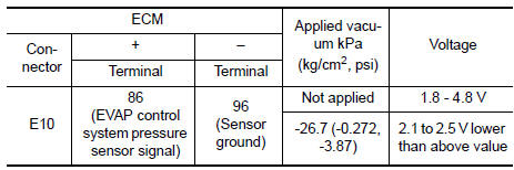
CAUTION:
- Always calibrate the vacuum pump gauge when using it.
- Never apply below -93.3 kPa (-0.952 kg/cm2, -13.53 psi) or pressure over 101.3 kPa (1.033 kg/cm2, 14.69 psi).
DRAIN FILTER
- Check visually for insect nests in the drain filter air inlet.
- Check visually for cracks or flaws in the appearance.
- Check visually for cracks or flaws in the hose.
- Blow air into port A and check that it flows freely out of port B.
- Block port B.
6. Blow air into port A and check that there is no leakage.
7. If NG, replace drain filter.
 P0452 evap control system pressure sensor
Description
The EVAP control system pressure sensor detects pressure in the
purge line. The sensor output voltage to the ECM increases as pressure
increases.
DTC Logic
DTC DETECTION LOGIC
...
 P0455 evap control system
DTC Logic
DTC DETECTION LOGIC
This diagnosis detects a very large leakage (fuel filler cap fell off etc.)
in EVAP system between the fuel tank
and EVAP canister purge volume control solenoid val ...
Other materials:
Shift lock release
If the battery charge is low or discharged, the
shift lever may not be moved from the P (Park)
position even with the brake pedal depressed
and the shift lever button pressed.
It will be necessary to jump start or have your
battery charged, For additional information, refer
to "Jump star ...
Timing Chain
Exploded View
Timing chain tensioner (secondary)
Internal chain guide
Timing chain tensioner (secondary)
Camshaft sprocket (EXH)
Timing chain (secondary)
Timing chain (primary)
Camshaft sprocket (INT)
Camshaft sprocket (INT)
Timing chain (secondary)
Camshaft sprocket (E ...
B26e1 no reception of engine status signal
Description
BCM receives the engine status signal from ECM via CAN
communication.
DTC Logic
DTC DETECTION LOGIC
NOTE:
If DTC B26E1 is displayed with DTC
U1000, first perform the trouble diagnosis for DTC U1000. Refer to
SEC-29, "DTC Logic".
If DTC B26E1 is displayed with D ...
Nissan Maxima Owners Manual
- Illustrated table of contents
- Safety-Seats, seat belts and supplemental restraint system
- Instruments and controls
- Pre-driving checks and adjustments
- Monitor, climate, audio, phone and voice recognition systems
- Starting and driving
- In case of emergency
- Appearance and care
- Do-it-yourself
- Maintenance and schedules
- Technical and consumer information
Nissan Maxima Service and Repair Manual

0.0105